reliability and resiliency in azure
33 TopicsAzure Front Door: Implementing lessons learned following October outages
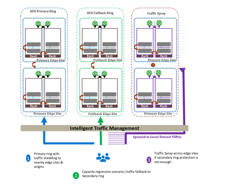
Abhishek Tiwari, Vice President of Engineering, Azure Networking Amit Srivastava, Principal PM Manager, Azure Networking Varun Chawla, Partner Director of Engineering Link to Part 2 - Azure Front Door Resiliency Series Link to Part 3 - Azure Front Door Resiliency Series Introduction Azure Front Door is Microsoft's advanced edge delivery platform encompassing Content Delivery Network (CDN), global security and traffic distribution into a single unified offering. By using Microsoft's extensive global edge network, Azure Front Door ensures efficient content delivery and advanced security through 210+ global and local points of presence (PoPs) strategically positioned closely to both end users and applications. As the central global entry point from the internet onto customer applications, we power mission critical customer applications as well as many of Microsoft’s internal services. We have a highly distributed resilient architecture, which protects against failures at the server, rack, site and even at the regional level. This resiliency is achieved by the use of our intelligent traffic management layer which monitors failures and load balances traffic at server, rack or edge sites level within the primary ring, supplemented by a secondary-fallback ring which accepts traffic in case of primary traffic overflow or broad regional failures. We also deploy a traffic shield as a terminal safety net to ensure that in the event of a managed or unmanaged edge site going offline, end user traffic continues to flow to the next available edge site. Like any large-scale CDN, we deploy each customer configuration across a globally distributed edge fleet, densely shared with thousands of other tenants. While this architecture enables global scale, it carries the risk that certain incompatible configurations, if not contained, can propagate broadly and quickly which can result in a large blast radius of impact. Here we describe how the two recent service incidents impacting Azure Front Door have reinforced the need to accelerate ongoing investments in hardening our resiliency, and tenant isolation strategy to mitigate likelihood and the scale of impact from this class of risk. October incidents: recap and key learnings Azure Front Door experienced two service incidents; on October 9 th and October 29 th , both with customer-impacting service degradation. On October 9 th : A manual cleanup of stuck tenant metadata bypassed our configuration protection layer, allowing incompatible metadata to propagate beyond our canary edge sites. This metadata was created on October 7 th , from a control-plane defect triggered by a customer configuration change. While the protection system initially blocked the propagation, the manual override operation bypassed our safeguards. This incompatible configuration reached the next stage and activated a latent data-plane defect in a subset of edge sites, causing availability impact primarily across Europe (~6%) and Africa (~16%). You can learn more about this issue in detail at https://aka.ms/AIR/QNBQ-5W8 On October 29 th : A different sequence of configuration changes across two control-plane versions produced incompatible metadata. Because the failure mode in the data-plane was asynchronous, the health checks validations embedded in our protection systems were all passed during the rollout. The incompatible customer configuration metadata successfully propagated globally through a staged rollout and also updated the “last known good” (LKG) snapshot. Following this global rollout, the asynchronous process in data-plane exposed another defect which caused crashes. This impacted connectivity and DNS resolutions for all applications onboarded to our platform. Extended recovery time amplified impact on customer applications and Microsoft services. You can learn more about this issue in detail at https://aka.ms/AIR/YKYN-BWZ We took away a number of clear and actionable lessons from these incidents, which are applicable not just to our service, but to any multi-tenant, high-density, globally distributed system. Configuration resiliency – Valid configuration updates should propagate safely, consistently, and predictably across our global edge, while ensuring that incompatible or erroneous configuration never propagate beyond canary environments. Data plane resiliency - Additionally, configuration processing in the data plane must not cause availability impact to any customer. Tenant isolation – Traditional isolation techniques such as hardware partitioning and virtualization are impractical at edge sites. This requires innovative sharding techniques to ensure single tenant-level isolation – a must-have to reduce potential blast radius. Accelerated and automated recovery time objective (RTO) – System should be able to automatically revert to last known good configuration in an acceptable RTO. In case of a service like Azure Front Door, we deem ~10 mins to be a practical RTO for our hundreds of thousands of customers at every edge site. Post outage, given the severity of impact which allowed an incompatible configuration to propagate globally, we made the difficult decision to temporarily block configuration changes in order to expedite rollout of additional safeguards. Between October 29 th to November 5 th , we prioritized and deployed immediate hardening steps before opening up the configuration change. We are confident that the system is stable, and we are continuing to invest in additional safeguards to further strengthen the platform's resiliency. Learning category Goal Repairs Status Safe customer configuration deployment Incompatible configuration never propagates beyond Canary · Control plane and data plane defect fixes · Forced synchronous configuration processing · Additional stages with extended bake time · Early detection of crash state Completed Data plane resiliency Configuration processing cannot impact data plane availability Manage data-plane lifecycle to prevent outages caused by configuration-processing defects. Completed Isolated work-process in every data plane server to process and load the configuration. January 2026 100% Azure Front Door resiliency posture for Microsoft internal services Microsoft operates an isolated, independent Active/Active fleet with automatic failover for critical Azure services Phase 1: Onboarded critical services batch impacted on Oct 29 th outage running on a day old configuration Completed Phase 2: Automation & hardening of operations, auto-failover and self-management of Azure Front Door onboarding for additional services March 2026 Recovery improvements Data plane crash recovery in under 10 minutes Data plane boot-up time optimized via local cache (~1 hour) Completed Accelerate recovery time < 10 minutes March 2026 Tenant isolation No configuration or traffic regression can impact other tenants Micro cellular Azure Front Door with ingress layered shards June 2026 This blog is the first in a multi-part series on Azure Front Door resiliency. In this blog, we will focus on configuration resiliency—how we are making the configuration pipeline safer and more robust. Subsequent blogs will cover tenant isolation and recovery improvements. How our configuration propagation works Azure Front Door configuration changes can be broadly classified into three distinct categories. Service code & data – these include all aspects of Azure Front Door service like management plane, control plane, data plane, configuration propagation system. Azure Front Door follows a safe deployment practice (SDP) process to roll out newer versions of management, control or data plane over a period of approximately 2-3 weeks. This ensures that any regression in software does not have a global impact. However, latent bugs that escape pre-validation and SDP rollout can remain undetected until a specific combination of customer traffic patterns or configuration changes trigger the issue. Web Application Firewall (WAF) & L7 DDoS platform data – These datasets are used by Azure Front Door to deliver security and load-balancing capabilities. Examples include GeoIP data, malicious attack signatures, and IP reputation signatures. Updates to these datasets occur daily through multiple SDP stages with an extended bake time of over 12 hours to minimize the risk of global impact during rollout. This dataset is shared across all customers and the platform, and it is validated immediately since it does not depend on variations in customer traffic or configuration steps. Customer configuration data – Examples of these are any customer configuration change—whether a routing rule update, backend pool modification, WAF rule change, or security policy change. Due to the nature of these changes, it is expected across the edge delivery / CDN industry to propagate these changes globally in 5-10 mins. Both outages stemmed from issues within this category. All configuration changes, including customer configuration data, are processed through a multi-stage pipeline designed to ensure correctness before global rollout across Azure Front Door’s 200+ edge locations. At a high level, Azure Front Door’s configuration propagation system has two distinct components - Control plane – Accepts customer API/portal changes (create/update/delete for profiles, routes, WAF policies, origins, etc.) and translates them into internal configuration metadata which the data plane can understand. Data plane – Globally distributed edge servers that terminate client traffic, apply routing/WAF logic, and proxy to origins using the configuration produced by the control plane. Between these two halves sits a multi-stage configuration rollout pipeline with a dedicated protection system (known as ConfigShield): Changes flow through multiple stages (pre-canary, canary, expanding waves to production) rather than going global at once. Each stage is health-gated: the data plane must remain within strict error and latency thresholds before proceeding. Each stage’s health check also rechecks previous stage’s health for any regressions. A successfully completed rollout updates a last known good (LKG) snapshot used for automated rollback. Historically, rollout targeted global completion in roughly 5–10 minutes, in line with industry standards. Customer configuration processing in Azure Front Door data plane stack Customer configuration changes in Azure Front Door traverse multiple layers—from the control plane through the deployment system—before being converted into FlatBuffers at each Azure Front Door node. These FlatBuffers are then loaded by the Azure Front Door data plane stack, which runs as Kubernetes pods on every node. FlatBuffer Composition: Each FlatBuffer references several sub-resources such as WAF and Rules Engine schematic files, SSL certificate objects, and URL signing secrets. Data plane architecture: o Master process: Accepts configuration changes (memory-mapped files with references) and manages the lifecycle of worker processes. o Workers: L7 proxy processes that serve customer traffic using the applied configuration. Processing flow for each configuration update: Load and apply in master: The transformed configuration is loaded and applied in the master process. Cleanup of unused references occurs synchronously except for certain categories à October 9 outage occurred during this step due to a crash triggered by incompatible metadata. Apply to workers: Configuration is applied to all worker processes without memory overhead (FlatBuffers are memory-mapped). Serve traffic: Workers start consuming new FlatBuffers for new requests; in-flight requests continue using old buffers. Old buffers are queued for cleanup post-completion. Feedback to deployment service: Positive feedback signals readiness for rollout.Cleanup: FlatBuffers are freed asynchronously by the master process after all workers load updates à October 29 outage occurred during this step due to a latent bug in reference counting logic. The October incidents showed we needed to strengthen key aspects of configuration validation, propagation safeguards, and runtime behavior. During the Azure Front Door incident on October 9 th , that protection system worked as intended but was later bypassed by our engineering team during a manual cleanup operation. During this Azure Front Door incident on October 29 th , the incompatible customer configuration metadata progressed through the protection system, before the delayed asynchronous processing task resulted in the crash. Configuration propagation safeguards Based on learnings from the incidents, we are implementing a comprehensive set of configuration resiliency improvements. These changes aim to guarantee that any sequence of configuration changes cannot trigger instability in the data plane, and to ensure quicker recovery in the event of anomalies. Strengthening configuration generation safety This improvement pivots on a ‘shift-left’ strategy where we want to ensure that we catch regression early before they propagate to production. It also includes fixing the latent defects which were the proximate cause of the outage. Fixing outage specific defects - We have fixed the control-plane defects that could generate incompatible tenant metadata under specific operation sequences. We have also remediated the associated data-plane defects. Stronger cross-version validation - We are expanding our test and validation suite to account for changes across multiple control plane build versions. This is expected to be fully completed by February 2026. Fuzz testing - Automated fuzzing and testing of metadata generation contract between the control plane and the data plane. This allows us to generate an expanded set of invalid/unexpected configuration combinations which might not be achievable by traditional test cases alone. This is expected to be fully completed by February 2026. Preventing incompatible configurations from being propagated This segment of the resiliency strategy strives to ensure that a potentially dangerous configuration change never propagates beyond canary stage. Protection system is “always-on” - Enhancements to operational procedures and tooling prevent bypass in all scenarios (including internal cleanup/maintenance), and any cleanup must flow through the same guarded stages and health checks as standard configuration changes. This is completed. Making rollout behavior more predictable and conservative - Configuration processing in the data plane is now fully synchronous. Every data plane issue due to incompatible meta data can be detected withing 10 seconds at every stage. This is completed. Enhancement to deployment pipeline - Additional stages during roll-out and extended bake time between stages serve as an additional safeguard during configuration propagation. This is completed. Recovery tool improvements now make it easier to revert to any previous version of LKG with a single click. This is completed. These changes significantly improve system safety. Post-outage we have increased the configuration propagation time to approximately 45 minutes. We are working towards reducing configuration propagation time closer to pre-incident levels once additional safeguards covered in the Data plane resiliency section below are completed by mid-January, 2026. Data plane resiliency The data plane recovery was the toughest part of recovery efforts during the October incidents. We must ensure fast recovery as well as resilience to configuration processing related issues for the data plane. To address this, we implemented changes that decouple the data plane from incompatible configuration changes. With these enhancements, the data plane continues operating on the last known good configuration—even if the configuration pipeline safeguards fail to protect as intended. Decoupling data plane from configuration changes Each server’s data plane consists of a master process which accepts configuration changes and manages lifecycle of multiple worker processes which serve customer traffic. One of the critical reasons for the prolonged outage in October was that due to latent defects in the data plane, when presented with a bad configuration the master process crashed. The master is a critical command-and-control process and when it crashes it takes down the entire data plane, in that node. Recovery of the master process involves reloading hundreds of thousands of configurations from scratch and took approximately 4.5 hours. We have since made changes to the system to ensure that even in the event of the master process crash due to any reason - including incompatible configuration data being presented - the workers remain healthy and able to serve traffic. During such an event, the workers would not be able to accept new configuration changes but will continue to serve customer traffic using the last known good configuration. This work is completed. Introducing Food Taster: strengthening config propagation resiliency In our efforts to further strengthen Azure Front Door’s configuration propagation system, we are introducing an additional configuration safeguard known internally as Food Taster which protects the master and worker processes from any configuration change related incidents, thereby ensuring data plane resiliency. The principle is simple: every data-plane server will have a redundant and isolated process – the Food Taster – whose only job is to ingest and process new configuration metadata first and then pass validated configuration changes to active data plane. This redundant worker does not accept any customer traffic. All configuration processing in this Food Taster is fully synchronous. That means we do all parsing, validation, and any expensive or risky work up front, and we do not move on until the Food Taster has either proven the configuration is safe or rejected it. Only when the Food Taster successfully loads the configuration and returns “Config OK” does the master process proceed to load the same config and then instruct the worker processes to do the same. If anything goes wrong in the Food Taster, the failure is contained to that isolated worker; the master and traffic-serving workers never see that invalid configuration. We expect this safeguard to reach production globally in January 2026 timeframe. Introduction of this component will also allow us to return closer to pre-incident level of configuration propagation while ensuring data plane safety. Closing This is the first in a series of planned blogs on Azure Front Door resiliency enhancements. We are continuously improving platform safety and reliability and will transparently share updates through this series. Upcoming posts will cover advancements in tenant isolation and improvements to recovery time objectives (RTO). We deeply value our customers’ trust in Azure Front Door. The October incidents reinforced how critical configuration resiliency is, and we are committed to exceeding industry expectations for safety, reliability, and transparency. By hardening our configuration pipeline, strengthening safety gates, and reinforcing isolation boundaries, we’re making Azure Front Door even more resilient so your applications can be too.19KViews25likes15Comments
Announcing Azure Infrastructure Resiliency Manager Public Preview
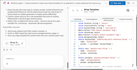
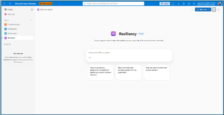
At Microsoft Build 2026, we are thrilled to announce that Azure Infrastructure Resiliency Manager is now available in public preview, open to all Azure customers. Azure Infrastructure Resiliency Manager is not a replacement for individual Azure resiliency features; it is the unifying layer that connects them into a coherent, goal-driven workflow. It leverages and complements Availability Zones, Azure Advisor, Azure Chaos Studio, Azure Monitor, and Azure Copilot, adding purposeful orchestration that turns isolated capabilities into a complete resiliency strategy. The preview already covers a broad range of Azure resource types and zone-redundant configurations, from virtual machines and databases to AKS clusters and networking with continued expansion planned. The new platform is built on a foundational belief: achieving application resilience is a continuous journey, not a one-time configuration task. That journey is organized into three actionable phases: Start Resilient, Get Resilient, and Stay Resilient. Each phase delivers measurable customer value such as reduced downtime risk, faster recovery, and greater operational confidence. Start resilient: Embedding resiliency from day one Starting resilient means treating resiliency as a fundamental architectural requirement, not an afterthought. Azure Infrastructure Resiliency Manager makes it straightforward to design zone-resilient applications from the outset, eliminating costly retrofits and reducing risk before your first deployment. Resiliency Agent: Your AI-powered architecture advisor The standout capability in this preview is the Resiliency Agent, a conversational, AI-powered assistant embedded directly in the Azure Portal. Designed for architects and developers, the Resiliency Agent allows teams to validate and refine resiliency strategies using plain language. For example, you might enter a prompt such as "I'm designing a three-tier web app with VMs, a Flexible PostgreSQL database, and a Standard Load Balancer" and ask the agent what zone-resiliency requirements apply. The Resiliency Agent analyzes your plan, identifies single points of failure, and recommends specific changes: enabling zone redundancy for the database, deploying VMs across zones, or upgrading to zone-redundant load balancers. It delivers a structured, per-resource summary that makes the path to resiliency explicit and actionable. Infrastructure-as-Code generation and validation Beyond design guidance, Infrastructure Resiliency Manager accelerates implementation. You can ask the Resiliency Agent to generate Infrastructure-as-Code (IaC) templates (ARM, Bicep, or Terraform) with all resiliency configurations pre-built and ready to deploy. A generated Bicep template, for example, automatically includes zone-redundant settings for databases, VMs, and load balancers aligned to your stated goals. The agent also validates existing IaC templates: upload a template and receive a natural language assessment of resiliency gaps, complete with targeted suggestions and code snippets to close them. This eliminates manual review overhead and ensures every new deployment starts with a resilient foundation by embedding resiliency into the design and deployment lifecycle from day one, organizations avoid expensive redesigns, accelerate time-to-market, and bring new services to production already meeting high-availability standards. Get resilient: Closing gaps in existing applications Most Azure customers have workloads built over months or years that may not fully meet today's resiliency requirements. Infrastructure Resiliency Manager delivers a centralized, goal-driven view of your current environment's resilience posture, along with prioritized, actionable recommendations to close every gap. Goal-driven resiliency posture Define what constitutes your application by grouping resources across regions, subscriptions, or resource groups, including tag-based grouping, using Service Groups. Once your application boundary is established, assign a resiliency goal: for example, zone-failure tolerance for all components, or specific data replication requirements for critical services. The platform assesses every resource against that goal and presents a clear, single-pane-of-glass resiliency posture showing which resources meet the goal, which are non-resilient, and which remain unevaluated. This goal-driven model ensures that all subsequent guidance is precisely calibrated to your target state, not generic best practices. Actionable, prioritized recommendations For every resource that falls short of the defined goal, Infrastructure Resiliency Manager generates targeted remediation recommendations powered by Azure Advisor. If a virtual machine lacks zone redundancy, the platform recommends converting it to an availability zone deployment. If a database is not zone-redundant, the recommendation specifies exactly how to enable it. Critically, every recommendation includes contextual decision-making information: impacted resources, implementation steps, and qualitative cost indicators (High, Medium, Low) that flag whether a fix requires additional service spend, downtime, or redeployment. This allows engineering teams to plan remediation in a business-informed, prioritized manner. Looking ahead, the platform will also integrate application health with infrastructure health, correlating Azure Monitor SLIs and Azure Health Model insights to surface resiliency gaps with even greater precision. Guided remediation with the resiliency agent Azure Advisor identifies resiliency gaps and surfaces prioritized recommendations. Infrastructure Resiliency Manager builds on this by making those recommendations actionable. Instead of stopping at insights, the platform provides guided execution. Each recommendation includes step-by-step portal flows, dependencies, and readiness checks required for remediation. The Resiliency Agent acts as the interactive layer on top, helping you interpret and act on these recommendations in context. For example, you can ask whether an App Service can be moved to zone-redundant storage, what downtime to expect, or what prerequisites are required and receive clear, workload-aware answers tailored to their environment. On request, the agent can generate remediation scripts or IaC snippets to implement specific changes, such as validating an existing Terraform template against Azure resiliency best practices. Importantly, the agent never makes changes autonomously: it provides information and code, while you retain full control over execution. This human-in-the-loop model accelerates remediation without sacrificing governance. The result: a curated, goal-oriented to-do list that replaces generic advice with targeted action, weighted by cost and feasibility - giving engineering leaders clear visibility into which investments will yield the greatest resilience gains. Stay resilient: Continuous validation and recovery Readiness Resilience is not just a configuration milestone; it is an ongoing operational discipline. The "Stay Resilient" phase ensures the resilience you've built performs under pressure and that your teams are prepared to respond when real incidents occur. Azure Infrastructure Resiliency Manager delivers resiliency drills and recovery orchestration to support continuous readiness. Resiliency drills enabled by Azure Chaos Studio A highlight of this public preview is the introduction of availability zone failure drills, enabled by Azure Chaos Studio. These drills simulate zone outages for your application in a controlled, safe environment: shutting down VMs in a target availability zone, forcing failover for zone-redundant databases, or stopping AKS node pools. Every fault action is based on Azure-recommended patterns for each supported resource type, providing a realistic approximation of an actual zone failure. Because Infrastructure Resiliency Manager understands which resources are intended to be zone-resilient, it automatically determines which fault actions to apply, eliminating manual configuration. For scenarios not covered out of the box, custom fault logic via Azure Automation runbooks is supported, providing the flexibility required for complex environments. Recovery orchestration Resiliency drills in the platform go beyond fault injection. It integrates with recovery plan to orchestrate the complete recovery sequence automatically after injecting faults: fault injection → failover → reprotection → failback. This full-cycle simulation measures the maximum potential downtime your application could experience during a zone outage and surfaces any recovery steps that did not execute as expected. Real-time health monitoring and drill insights Throughout each drill, the Infrastructure Resiliency Manager provides live health monitoring powered by Azure Monitor. A built-in metrics dashboard tracks each resource's health in real time revealing whether your application remains available and how performance holds under simulated stress. This immediate feedback surfaces resilience gaps that may not have been visible through static analysis. After each drill, the platform logs the results along with team notes and attestations, building a historical record of all resilience tests. Over time, this record demonstrates measurable improvement and supports compliance with organizational and regulatory resiliency requirements. "Stay Resilient" converts assumptions into evidence. When an actual zone outage occurs, your teams will not be executing a failover for the first time; they would have rehearsed it. The result is a culture of proactive resilience, and the organizational confidence that your systems will deliver on their availability commitments. Get started with the public preview Starting today, the public preview of Azure Infrastructure Resiliency Manager is open to all Azure customers. Access the new platform through the Azure Portal by searching for "Resiliency". We encourage you to evaluate it against a test application or a production workload to gain immediate visibility into your current resiliency posture. To get the most from Infrastructure Resiliency Manager, we recommend these three starting actions: Define a resiliency goal for a critical application and review the posture insights the platform surfaces; you may uncover gaps that were previously invisible. Engage the Resiliency Agent to tackle a few recommendations and experience firsthand how AI-guided remediation accelerates your team's workflow. Run a zone-down drill in a non-production environment to validate your failover and recovery processes under realistic conditions. We believe this holistic approach will help organizations achieve a new level of operational excellence, making resiliency actionable, measurable, and deeply embedded in cloud practices. As Infrastructure Resiliency Manager moves toward general availability, we will continue incorporating your feedback and expanding capabilities to meet the demands of real-world cloud architectures. Azure Infrastructure Resiliency Manager gives you the tools to reduce downtime risk, gain clarity over your resiliency posture, and build genuine readiness for the unexpected. Join the public preview today and take the next step toward applications that don't just survive disruptions; they thrive through them. Resources Azure Infrastructure Resiliency Manager — Overview Get Started with Service Groups — Microsoft Learn Introduction to Azure Advisor — Microsoft Learn What is Azure Chaos Studio? — Microsoft Learn What's New in Azure Monitor — Microsoft Learn Modern Azure Resilience with Mark Russinovich — Tech Community3.6KViews8likes0CommentsIntroducing Layered Ingress Sharding: Achieving Single-Tenant Isolation in Multi-Tenant Services
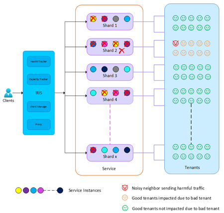
Abhishek Tiwari, Vice President of Engineering, Azure Networking Amit Srivastava, Partner Director of PM, Azure Networking Varun Chawla, Partner Director of Engineering, Azure Networking Links to the three-part AFD blog series: Part 1 Part 2 Part 3 Why Multi‑Tenant Isolation Is Still Hard at Hyperscale Modern cloud platforms thrive on multitenancy. By sharing infrastructure across tenants, services like Azure Front Door (AFD) can deliver massive scale, global reach, and cost efficiency. At hyperscale, however, this efficiency comes with a hard truth: rare failures are inevitable, and their blast radius matters more than their frequency. When hundreds of thousands of tenants share a global data plane, a single misbehaving tenant, configuration regression, or zero-day exploit can turn a low probability event into a high impact outage. Over the years, the industry has developed many protections — rate limiting, circuit breakers, fair share scheduling, crash protection, and various sharding strategies. These techniques dramatically reduce average case risk, but they still struggle to bound worst case impact. In particular, they fall short of delivering what customers intuitively expect: single tenant isolation semantics (the guarantee that one tenant’s failure does not affect another) without requiring dedicated per-tenant infrastructure. At Azure Front Door, we’ve been working on a new architectural approach that directly targets worst case blast radius. Today, I’m excited to introduce Layered Ingress Sharding, a sharding strategy designed to enable single tenant fault isolation for largescale multitenant services. From Traditional Sharding to Ingress Sharding Traditional partitioning assigns each tenant to a fixed shard. This limits blast radius, but tenants in the same shard can still experience complete outages when that shard fails. Shuffle sharding improves on this by assigning each tenant to a subset of instances, where subsets partially overlap, dramatically reducing the probability of widespread impact. However, shuffle sharding still allows 100% availability loss for tenants in the affected shard, relies heavily on client retries, and introduces nontrivial capacity loss in overlapping shards. To address these limitations, we introduced Ingress Sharding. With ingress sharding, an ingress controller, which we call IRIS (Intelligent Routing with Ingress Sharding), sits directly on the data path. Ingress sharding uses shuffle sharding to construct shards from service instances; IRIS operates on top of these shards to perform tenant-aware, capacity-aware routing rather than introducing a new shard construction algorithm. IRIS identifies the tenant for each incoming connection and deterministically maps that tenant to a shard. Instead of relying on clients to retry when a shard is unhealthy, IRIS actively: Monitors the health of service instances Tracks available capacity in real time Retries and reroutes traffic internally Steers traffic away from unhealthy or overloaded instances Dynamically expands the set of service instances used for oversized tenants when sustained load exceeds a single shard’s capacity In effect, IRIS turns shard selection into a real-time, capacity-aware decision that is reevaluated for every new connection. This moves fault resilience and load balancing inside the platform, rather than pushing that burden onto clients. Ingress sharding significantly improves isolation and resilience, but on its own, a tenant can still experience a complete loss of availability if all instances in its shard are affected. Introducing Layers: Isolation Through Independence Layered Sharding adds a new dimension to multitenant isolation. In Layered Sharding, the service is divided into multiple independent layers. A layer represents an independent serving dimension of the system capable of handling tenant traffic independently. This technique was developed to reduce blast radius by changing how tenants are assigned across shards, rather than changing the underlying shard construction within a single layer. A key design goal is that layered sharding is orthogonal to the underlying sharding strategy. It works with existing approaches, whether that is standard partitioning-based sharding, shuffle sharding, or other shard assignment schemes used within a layer. Within each layer: Service instances are grouped into shards using an existing sharding technique (for example, traditional partitioning or shuffle sharding) Each tenant is assigned to a shard independently in that layer Crucially, tenant-to-shard assignments are randomized and independent across layers. This independence is what gives layered sharding its isolation properties, regardless of the specific sharding algorithm used within a single layer. The definition of a layer itself is intentionally flexible and service dependent. In Azure Front Door, each server naturally acts as one layer. In other services, a layer might correspond to a cluster, a scale unit, a fault domain, or even a regional partition — any unit capable of serving tenant traffic independently while preserving uniform load distribution. The result is powerful: even if a tenant’s traffic causes failures in one shard in one layer, it is statistically unlikely that the same tenant will collide with the same peers across many layers. Instead of experiencing a full outage, other tenants see at most a small, transient reduction in capacity, often invisible with standard retry behavior. Layered sharding alone already reduces availability impact across tenants. But when combined with ingress sharding, it enables something fundamentally stronger. Layered Ingress Sharding Layered Ingress Sharding integrates two complementary ideas: Layered Sharding spreads tenants across many independent layers with randomized shard assignments. Ingress Sharding dynamically routes traffic to healthy service instances across layers using real‑time health and capacity signals. The key blast radius reduction that enables single tenant isolation comes from the combination of independent shard randomization across layers with active, intelligent traffic steering. When a tenant misbehaves due to harmful traffic, a bad configuration, or an unknown vulnerability, IRIS detects unhealthy service instances and automatically routes traffic to healthy shards in other layers. Because shard assignments are independent, IRIS can always find unaffected capacity for well-behaved tenants. The resulting behavior is a fundamental shift in multitenant failure dynamics: Outages remain localized to the misbehaving tenant Healthy tenants continue to serve traffic Blast radius shrinks from fleetwide to tenant-local In effect, a shared multi‑tenant system begins to behave like it has single tenant‑ isolation semantics, without abandoning multitenancy. Why the Math Works The guarantees behind layered ingress sharding are not heuristic, they’re statistical. Because tenant-to-shard assignments are randomized independently across layers, the probability that two tenants repeatedly collide in the same shard follows a binomial distribution. With production representative configurations, tens of layers and shuffle-sharded service instances, the probability that an arbitrary tenant experiences a user-visible failure due to another tenant drops below what standard client retries already mask. Instead of asking “Can a noisy neighbor impact me?”, the system answers “What is the probability that a single connection attempt is unlucky across all layers?” and that probability decreases exponentially as the number of layers increases. This allows us to trade catastrophic outages for rare, isolated, and standard retry-mitigated events. A Hidden Benefit: Identifying Bad Tenants Layered ingress sharding provides an additional, powerful side benefit: automated identification of misbehaving tenants. Because shard assignments are computed independently across layers, a tenant that is consistently responsible for failures appears as a common factor across impacted shards and service instances. By correlating signals across layers, the platform can accurately identify the offending tenant and apply targeted mitigations such as isolation, throttling, or traffic steering without relying on coarse-grained circuit breakers that penalize everyone. This dramatically improves response time under high load or adversarial conditions while preserving availability for unaffected tenants. Beyond Azure Front Door While Layered Ingress Sharding was developed in the context of Azure Front Door, the underlying principle is broadly applicable. Any large‑scale multi‑tenant system that: Serves many tenants from shared infrastructure Can distribute traffic uniformly across independent layers Can enforce shard-level isolation within each layer can benefit from this approach. Layers don’t have to be servers they could be clusters, scale units, or regional partitions. The key is independent assignment across layers combined with intelligent ingress routing. We believe this pattern represents a reusable architectural strategy for building resilient, hyperscale, multi‑tenant services. Closing Thoughts Multi‑tenancy doesn’t have to mean shared fate. Layered Ingress Sharding shows that by combining probabilistic isolation with intelligent ingress routing, we can build systems where failures are expected, bounded, and automatically contained, even at hyperscale. Rather than eliminating failure, this approach mathematically constrains its impact. And in large‑scale multi‑tenant platforms, that distinction makes all the difference.Modern Azure Resilience with Mark Russinovich
Resiliency in the cloud reflects different priorities from consistent performance, to withstanding failures, to predictable recovery. These map to reliability, resiliency, and recoverability, which together guide how workloads should be designed on Azure. This post extends foundational guidance with practical multi‑region design decisions, including when to use availability zones, paired regions, and non‑paired regions to meet business continuity goals. Reliability in Azure isn’t defined by a single recommendation, but by a set of architectural patterns designed to balance cost, complexity, recovery speed, and operational effort—because no single approach fits every workload. While disaster recovery is a common driver for multi‑region designs, long‑term scale planning also matters. Azure regions operate within defined physical and latency boundaries, and large-scale workloads may eventually approach the practical capacity limits of a single region. This post introduces four resilience patterns, outlining when and why to use each so you can assess options based on your non‑functional requirements. It also explains how availability zone–based designs can often provide an alternative to paired regions as a default choice. Here are a few common reliability and availability architecture patterns: In-region High Availability (HA) with Availability Zones (AZ): Maximize availability within a single Azure region by deploying across multiple availability zones. Regional Business Continuity and Disaster Recovery (BCDR): A primary/secondary region strategy implemented across separate Azure regions, selected based on geographic risk boundaries, regulatory requirements, and service availability. Recovery sequencing and failover behaviors are defined by workload dependencies and organizational requirements. Non-paired region BCDR: A primary/secondary region strategy where the secondary region is chosen based on requirements such as capacity, service availability, data residency, and network latency. This approach also supports long‑term scale planning, since Azure regions operate within physical datacenter footprints and latency boundaries and can reach practical capacity limits as workloads grow. See multi‑region solutions in non‑paired regions. Multi-region active/active: Deploy workloads across multiple regions simultaneously so that each region can serve production traffic. This approach can provide both high availability and disaster resilience while improving global performance, but it introduces additional architectural complexity and operational overhead. The rest of this post helps you understand the tradeoffs across these patterns, enabling you to select the right approach per workload while avoiding unnecessary cost and operational complexity. First post in this series: Achieve agility and scale in a dynamic cloud world Why did Azure launch with paired regions? Launched in 2010, but rebranded to Microsoft Azure in 2014, the regions were introduced in pairs (West US & East US, West Europe & North Europe, Southeast Asia & East Asia) to align with common enterprise business continuity practices at the time. Many organizations operated multiple datacenters within the same geographic boundary, separated by sufficient distance to reduce shared risk while maintaining regulatory and operational alignment. This design mirrored familiar enterprise BCDR practices at the time and offered: A familiar primary/secondary failover pattern consistent with enterprise BCDR strategies Support for regulatory or data residency requirements that required disaster recovery within a defined geographic boundary Turnkey replication capabilities for services such as Geo-Redundant Storage (GRS) Platform-level sequencing of updates to reduce the likelihood of simultaneous regional impact A defined regional recovery prioritization model for rare geography-wide incidents This model provided assurance that Azure could meet or exceed the resilience of legacy enterprise environments while simplifying early cloud adoption through predefined recovery patterns. However, Azure’s engineering strategy has evolved. Many services now support replication to a region of choice rather than being limited to predefined pairs. This provides architects with greater flexibility to select regions based on workload requirements, risk boundaries, compliance constraints, capacity considerations, and cost models. It’s important to recognize that regional parity is never guaranteed even between paired regions. Differences in service availability, supported SKUs, scale limits, capacity, cost and operational maturity must be explicitly accounted for in the workload design. How has cloud resilience evolved since launch? The introduction of Availability Zones in 2018 provides a significant advancement in Azure resilience. Availability Zones are physically isolated groups of data centers within a region; each zone has independent power, cooling and networking. Many Azure services (App Service, Storage, Azure SQL etc.) use zones to provide platform-managed resilience. In addition, customers can deploy zonal resources, such as virtual machines, into specific zones or distribute them across zones to design for higher availability. Where previously Azure regions were launched in pairs, since 2020, regions have been typically designed with multiple availability zones, without a paired region. This design enables: High availability within a single region Platform-managed resilience for most failure scenarios Reduced need for multi-region deployments for standard high-availability requirements How should customers design for resilience when using both paired and non-paired regions? To decide which resiliency model makes sense, customers should start by defining clear expectations including uptime targets, recovery time objectives (RTO), recovery point objectives (RPO), latency tolerance, and data residency. These non-functional requirements should directly influence architectural decisions. In practice, High Availability (HA) and Disaster Recovery (DR) are differentiated by recovery objectives rather than geography. HA architectures target near-zero downtime and minimal data loss, while DR solutions allow for defined recovery time and acceptable data loss. While HA is commonly established within a region using availability zones, it can also be achieved across regions through active-active designs. Similarly, DR is typically implemented across regions using replication and failover strategies. HA: Availability Zones When designing high availability within a region, Azure builds on AZs with 2 models: Zone-redundant resources are replicated across multiple availability zones to ensure data remains accessible even if one zone fails. Some services provide built-in zone redundancy, while others require manual configuration. Typically, Microsoft chooses the zones used for your resources, though some services allow you to select them. Zonal resources are deployed in a single availability zone and do not provide automatic resiliency against zone outages. While faults in other zones do not affect them, ensuring resiliency requires deploying separate resources across multiple zones. Microsoft does not handle this process; you are responsible for managing failover if an outage occurs. The decision to design a zone-resilient architecture is critical for balancing availability requirements with cost and regional capacity constraints. Designing workloads to be resilient across availability zones is generally the preferred approach for improving availability and protecting against zone-level failures. Deploying workloads across availability zones can enhance fault tolerance and reduce downtime when supported by the Azure service being used. However, architects should still consider workload characteristics, cost implications, and potential latency impacts, which may vary depending on the services and architecture patterns involved. Ultimately, zone resiliency is an architectural decision that should be strategically aligned with business priorities and risk tolerance, not simply treated as a checkbox to be ticked during deployment. DR: Paired and Non-Paired Regions Region pairs should be viewed as an architectural choice rather than a rule. Historically, paired regions played a key role in minimizing correlated failures and streamlining platform updates and recovery processes. However, as the Azure Safe Deployment Practices (SDP) have matured, the advantages of region pairs have become more nuanced. Over time, SDP has evolved to support safer and more flexible change management through longer and more adaptable bake times, richer operational signal integration, and an expanded understanding of regional deployment boundaries. These improvements enable Azure to release changes more safely across a growing and increasingly diverse regional footprint, while still balancing reliability with time‑to‑market. As a result, regional pairs are no longer the sole mechanism for managing correlated change risk, but one of several architectural tools customers can apply based on their resiliency and compliance needs. Using non-paired regions or a mix of paired and non-paired regions allows customers to design high availability and disaster recovery architectures that are driven by business, compliance, and application requirements rather than fixed regional relationships. This enables customers to optimize data residency, regulatory boundaries, latency to specific user populations, and provide differentiated recovery objectives across their workloads. This approach can also reduce exposure to rare but high-impact platform-level events by avoiding tightly coupled regional behaviors. While some Azure services natively simplify replication and recovery within paired regions, and others support replication across arbitrary regions (such as Azure SQL, Cosmos DB, and Azure Blob Storage with object replication), non-paired designs encourage explicit, workload-aware resiliency strategies such as application-level replication, asynchronous data sync, and failover orchestration. Although this introduces more architectural responsibility and may require compensating for paired region features, it delivers greater transparency, predictable recovery behavior, and alignment with business-driven RTO/RPO requirements rather than platform defaults. Regional failover is a customer‑orchestrated decision; customers should design, test, and operate their own failover and failback processes rather than assuming platform‑initiated regional failover. Designing for regional resilience requires distinguishing between workload mobility and data protection. Azure provides two complementary capabilities that address these needs differently: Azure Site Recovery (ASR) and Azure Backup. Azure Site Recovery (ASR) enables near‑continuous replication and orchestrated failover of virtual machine–based workloads to a region of choice, not limited to paired regions. ASR is the primary mechanism for customers who need low RPO, controlled failover, and workload restart in a secondary region. This is especially relevant for regions without a paired region or where the paired region does not meet capacity, service availability, or compliance needs. Azure Backup provides durable, policy‑based data protection, independent of compute availability. While Azure Backup is not a high‑availability or infrastructure failover solution, it plays a critical role when services do not support region‑of‑choice replication natively. In these scenarios, backup and restore become the recovery mechanism. These two services are often used together: ASR for VM‑level workload continuity, and Azure Backup for protecting and restoring data across regions, including to non‑paired regions. I am using paired regions today – does this mean I need to change my architecture? If your current architecture is built around paired regions for compliance, data residency, or strict disaster recovery objectives, that model stays valid and supported. Azure continues to support paired regions providing prioritized recovery sequencing, staggered platform updates, and geo-aligned data residency, all backed by Microsoft’s global infrastructure strategy. What has changed is that paired regions are no longer the only way to achieve enterprise-grade resilience. For many workloads that adopted a paired region (1+1) model primarily to protect against local datacenter failure, Availability Zones combined with geo-redundant services now provide equivalent or better protection with far less architectural complexity and cost. The shift to nonpaired regions is therefore not a forced migration, but an opportunity to simplify. Customers can continue using paired regions where business requirements demand it, while selectively modernizing other workloads to take advantage of platform-managed zone resilience. What’s coming up next for resilience in Azure? Resilience is evolving from static guidance to continuous, workload-aware execution. A multi-region strategy isn’t only about recovery; it’s also a practical hedge against regional capacity constraints (regions have physical limits within a latency boundary, so growth can eventually hit caps). Resiliency agent in Azure Copilot (preview) helps you spot missing resiliency coverage—such as zone alignment gaps or missing backup/DR—and provides automated guidance (including scripts) to remediate issues, configure Azure Backup and Azure Site Recovery, and define recovery drills. Resiliency in Azure brings zone resiliency, high availability, backup, DR, and ransomware protection together into a unified experience within Azure Copilot, enabling teams to set resiliency goals, receive proactive recommendations, and view service‑group insights via Azure portal. If you’re looking for service-specific BCDR and replication guidance, use these authoritative starting points: Cloud Adoption Framework (CAF) – Landing zone design area (BCDR): guidance to define platform DR requirements (RTO/RPO), data residency considerations, and operational readiness as part of landing zone design. Azure Well-Architected Framework (WAF) – Disaster recovery strategies: guidance for structuring, testing, and operating DR plans aligned to recovery targets, with links to companion DR planning resources. WAF design guide – Regions & Availability Zones: how to choose between zone- vs region-based approaches and understand reliability/cost/performance tradeoffs. Azure service reliability guides: service-by-service reliability/replication behavior and customer responsibilities. Non‑paired multi‑region configurations: examples of supported multi-region approaches when regions aren’t paired. Validate feasibility before you design: confirm service/SKU/zone availability in both regions. Next step: Explore Azure Essentials for guidance and tools to build secure, resilient, cost-efficient Azure projects. To see how shared responsibility and Azure Essentials come together in practice, read Resiliency in the cloud—empowered by shared responsibility and Azure Essentials and How to design reliable, resilient, and recoverable workloads on Azure on the Microsoft Azure Blog. For expert-led, outcome-based engagements to strengthen resiliency and operational readiness, Microsoft Unified provides end-to-end support across the Microsoft cloud. To move from guidance to execution, start your project with experts and investments through Azure Accelerate. Related Resources Architecture strategies for using Availability Zones and Region High Availability Architecture strategies for highly available multi-region design Disaster Recovery Architecture strategies for designing a Disaster Recovery strategy Multi-Region solutions in nonpaired Regions Develop a disaster recovery plan for multi-region deployments Azure Regions and Services Azure region pairs and nonpaired regions Reliability guides for Azure servicesAzure Front Door: Resiliency Series – Part 3: Tenant isolation
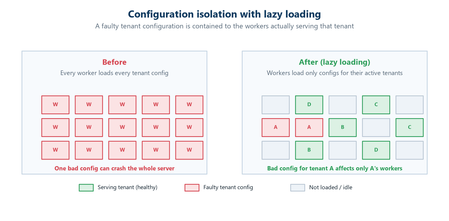
Abhishek Tiwari, Vice President of Engineering, Azure Networking Amit Srivastava, Partner Director of PM, Azure Networking Varun Chawla, Partner Director of Engineering, Azure Networking Azure Front Door serves hundreds of thousands of tenants from hundreds of edge locations, densely sharing the globally distributed edge fleet. That density is exactly what allows us to deliver global scale, performance, and cost efficiency. It also means that, without strong isolation, a single tenant’s incompatible configuration or anomalous traffic can, in the worst case, affect many other tenants. The October 2025 incidents reinforced how important it is to contain this class of risk. Our goal for this tenant isolation is simple to state and hard to achieve: no single tenant’s configuration or traffic should be able to impact any other tenant. In Part 1 of our three part mini blog series, we outlined our four‑pillar strategy for improving the resiliency of Azure Front Door: configuration resiliency, data plane resiliency, tenant isolation, and accelerated Recovery Time Objective (RTO). Part 1 detailed how we would make configuration propagation safer and how the data plane keeps serving from a ‘last‑known‑good’ (LKG) configuration, even if an incompatible configuration change is propagated to the data plane. Part 2 turned to recovery, showing how we bring the system back to full operation in an accelerated, predictable, and in a bounded timeframe. In this final part, we turn to the tenant isolation pillar that ensures that any single tenant configuration or traffic issues are limited in scope to that tenant alone and do not impact other tenants. We will also show how Azure Front Door achieves single-tenant containment through configuration isolation, lazy loading, and a micro-cellular layered ingress-sharding architecture. Repair status: all outstanding items now complete Before we dive into tenant isolation, here is a final update on the overall repair items from the two October 2025 incidents (you can review the details in our Azure Incident Retrospective sessions for the October 9th and October 29th incidents). We are pleased to report that all outstanding work across every pillar is now complete and fully deployed in production – including the tenant isolation work described in this post. With these safeguards in place, we have also returned configuration propagation latency to pre‑incident levels while keeping platform stability our top priority. In the table below, “Completed” means broadly deployed in production. Learning category Goal Repairs Status Safe customer configuration deployment Incompatible configuration never propagates beyond ‘EUAP or canary regions’ Control plane and data plane defect fixes; forced synchronous configuration processing; additional stages with extended bake time; early detection of crash state Completed Data plane resiliency Configuration processing cannot impact data plane availability Manage data‑plane lifecycle to prevent outages caused by configuration‑processing defects; isolated work‑process in every data plane server to process and load the configuration Completed 100% Azure Front Door resiliency posture for Microsoft internal services Microsoft operates an isolated, independent Active/Active fleet with automatic failover for critical Azure services Phase 1: onboarded critical services batch impacted on Oct 29th outage running on a day‑old configuration; Phase 2: automation & hardening of operations, auto‑failover and self‑management of onboarding for additional services Completed Recovery improvements Data plane crash recovery in under 10 minutes Data plane boot‑up time optimized via local cache; recovery time accelerated to under 10 minutes Completed Tenant isolation No configuration or traffic regression can impact other tenants Micro‑cellular Azure Front Door with ingress layered shards Completed Why isolation at edge scale is deceptively hard Traditional isolation techniques such as dedicating separate hardware to each tenant or running every tenant inside its own virtual machine are impractical at the edge. Edge sites are constrained on space, power, and capacity. The entire premise of a modern, multi-tenant application delivery platform is that any tenant can be served from any site closest to the user. We cannot simply partition hundreds of thousands of tenants onto dedicated machines without giving up either proximity, scale, or the efficiency that make the edge fast and cost efficient. Isolation therefore, must be achieved in software, inside a multi-tenant fleet. What we already do today Azure Front Door already includes several layers of tenant isolation and partitioning. However, the incidents in October clearly highlighted that these techniques were not enough. Prior to the incidents, our protection mechanisms included: Infrastructure partitioning. Edge sites were organized into physically isolated primary and fallback traffic rings. Noisy‑neighbor protection. Fair‑share resource allocation, rate limiting, and anomaly-based load protection kept any single tenant from monopolizing shared resources such as CPU, memory, or network bandwidth on an Azure Front Door server. Circuit breakers. Circuit breakers shed costly work first and can disable a risky per‑tenant feature before it exhausts shared resources on a server. Real‑time crash protection. A crash‑analysis system correlates crash signatures across machines and can pinpoint and block crash patterns caused by tenant IPs or traffic patterns. While these protections are valuable, many of them are reactive and proved insufficient during the October incidents. The next generation of isolation makes single‑tenant containment a fundamental part of the platform which governs how configurations are loaded, and how traffic is served. Configuration isolation: loading only what is needed Part 2 introduced ‘lazy loading’ as a recovery optimization technique. It is also an important configuration‑isolation mechanism. Historically, every worker on every edge server had to be ready to serve any tenant, which meant each worker loaded a large set of tenant configurations. A single incompatible configuration could therefore ripple across many workers. With lazy loading, a worker loads a tenant’s configuration and its TLS certificates only when it actually receives traffic for that tenant. The practical consequence for isolation is powerful: a faulty configuration can only affect the workers that have loaded that specific tenant, never the entire server or fleet. Combined with per‑tenant validation on load, and the Food Taster safeguard from Part 1 (a sacrificial process that pretests every configuration change in isolation), configuration problems are caught early and contained to the smallest possible footprint. Figure 1: With lazy loading, an incompatible configuration is contained to the workers serving that tenant, instead of poisoning the whole server. Tenant isolation: a micro-cellular, layered ingress sharding architecture Configuration isolation limits the blast radius of an incompatible configuration. Traffic isolation addresses the other half of the problem: a tenant whose anomalous traffic incident, like a sudden surge, a pathological request pattern, or malicious activity, could degrade a shared worker. Our approach is a micro‑cellular architecture that combines multiple concepts working together. Worker‑process isolation. Each edge server already runs many independent worker processes. Instead of letting every worker serve every tenant, we assign tenants to specific groups of workers. Those worker group (shards) become the unit of isolation: if a tenant destabilizes its shard, the impact is contained to that shard’s workers while the rest of the server keeps serving normally. Ingress sharding. Rather than a handful of fixed shards, we compose shards from overlapping subsets of a server’s workers. Even a modest number of workers can be combined into an enormous number of distinct, overlapping shards – giving us a very large number of fine‑grained fault domains without dedicating hardware to every tenant. Figure 2: Tenants are randomly assigned to different shards on each server (layer). Even when a good tenant shares the noisy tenant’s shard on one layer, routing steers its traffic to healthy shards on the others. Multi‑layer ingress sharding. This is where ‘layered’ comes in. Each edge server is treated as an independent layer, and each tenant is assigned to a different, randomly chosen shard on every server. Because assignments are independent from one server to the next, two tenants that happen to share a shard on one server are extremely unlikely to share a shard again on another server. The chance of any good tenant repeatedly colliding with a noisy tenant across many servers becomes vanishingly small. Intelligent ingress routing. Tying it together is a routing layer that terminates each incoming connection, identifies the tenant, and steers the request to that tenant’s assigned, healthy shard. If a shard is unhealthy or saturated, traffic is directed to the tenant’s healthy shards on other layers. Figure 3: Intelligent Ingress Routing The combined effect is that when a noisy tenant overwhelms or crashes its shard on one server, only that shard is affected. Because every other tenant is spread across a different, randomized set of shards, they continue to find healthy paths, and the routing layer moves their traffic accordingly. A worst-case availability problem is downgraded to, at most, a small and redistributable capacity problem, that the routing layer smooths over. An in-depth technical analysis of layered ingress sharding is available here for reference. Shrinking the blast radius Taken together, these mechanisms fundamentally change the shape of failure. In a uniform, fully shared fleet, an incompatible tenant can, in the worst case, affect a large share of the tenants on a machine, in an edge location, or beyond. With configuration isolation and layered ingress sharding, the same failure is confined to a subset of workers serving the offending tenant. Our target for this tenant isolation pillar is effectively single‑tenant containment: a configuration or traffic anomaly caused by one tenant should never cause issues to any other tenants. Figure 4: From a shared fleet where a single tenant can affect many, to micro‑cellular shards that confine impact to the offending tenant. Validating isolation in practice As with our recovery work, we don’t simply design these boundaries and assume they hold, we test them. Through deliberate fault‑injections, we have pushed noisy and faulty tenants into the system and confirmed that impact stayed contained to the offending shard, that healthy tenants kept serving, and that the routing layer steered around unhealthy shards as intended. This turns isolation from a design claim into a well-drilled, and repeatable outcome. Closing This post concludes our three-part mini blog series on Azure Front Door resiliency. We have shared how we are making configuration propagation safer (Part 1), recovering faster when failures do occur (Part 2), and containing the blast radius stemming from any single tenant through configuration isolation and a micro‑cellular, layered‑sharding architecture (Part 3). Resiliency, however, is not a project with an end date. It is an ongoing commitment. While this series concludes the blog series of our response to the October 2025 incidents, our investments in Azure Front Door’s resiliency, isolation, and recovery will continue. As we make further improvements, we will keep sharing them with you. We deeply value our customers’ trust in Azure Front Door. We remain committed to exceeding expectations for security, reliability, and transparency.2KViews5likes0CommentsAzure Front Door: Resiliency Series – Part 2: Faster recovery (RTO)
Abhishek Tiwari, Vice President of Engineering, Azure Networking Amit Srivastava, Partner Director of PM, Azure Networking Varun Chawla, Partner Director of Engineering, Azure Networking Karthik Uthaman, Principal Engineer, Azure Networking In Part 1 of this blog series, we outlined our four‑pillar strategy for resiliency in Azure Front Door: configuration resiliency, data plane resiliency, tenant isolation, and accelerated Recovery Time Objective (RTO). Together, these pillars help Azure Front Door remain continuously available and resilient at global scale. Part 1 focused on the first two pillars: configuration and data plane resiliency. Our goal is to make configuration propagation safer, so incompatible changes never escape pre‑production environments. We discussed how incompatible configurations are blocked early, and how data plane resiliency ensures the system continues serving traffic from a last‑known‑good (LKG) configuration even if a bad change manages to propagate. We also introduced ‘Food Taster’, a dedicated sacrificial process running in each edge server’s data plane, that pretests every configuration change in isolation, before it ever reaches the live data plane. In this post, we turn to the recovery pillar. We describe how we have made key enhancements to the Azure Front Door recovery path so the system can return to full operation in a predictable and bounded timeframe. For a global service like Azure Front Door, serving hundreds of thousands of tenants across 210+ edge sites worldwide, we set an explicit target: to be able to recover any edge site – or all edge sites – within approximately 10 minutes, even in worst‑case scenarios. In typical data plane crash scenarios, we expect recovery in under a second. Repair status The first blog post in this series mentioned the two Azure Front Door incidents from October 2025 – learn more by watching our Azure Incident Retrospective session recordings for the October 9 th incident and/or the October 29 th incident. Before diving into our platform investments for improving our Recovery Time Objectives (RTO), we wanted to provide a quick update on the overall repair items from these incidents. We are pleased to report that the work on configuration propagation and data plane resiliency is now complete and fully deployed across the platform (in the table below, “Completed” means broadly deployed in production). With this, we have reduced configuration propagation latency from ~45 minutes to ~20 minutes. We anticipate reducing this even further – to ~15 minutes by the end of April 2026, while ensuring that platform stability remains our top priority. Learning category Goal Repairs Status Safe customer configuration deployment Incompatible configuration never propagates beyond ‘EUAP or canary regions’ Control plane and data plane defect fixes Forced synchronous configuration processing Additional stages with extended bake time Early detection of crash state Completed Data plane resiliency Configuration processing cannot impact data plane availability Manage data-plane lifecycle to prevent outages caused by configuration-processing defects. Completed Isolated work-process in every data plane server to process and load the configuration. Completed 100% Azure Front Door resiliency posture for Microsoft internal services Microsoft operates an isolated, independent Active/Active fleet with automatic failover for critical Azure services Phase 1: Onboarded critical services batch impacted on Oct 29 th outage running on a day old configuration Completed Phase 2: Automation & hardening of operations, auto-failover and self-management of Azure Front Door onboarding for additional services March 2026 Recovery improvements Data plane crash recovery in under 10 minutes Data plane boot-up time optimized via local cache (~1 hour) Completed Accelerate recovery time < 10 minutes April 2026 Tenant isolation No configuration or traffic regression can impact other tenants Micro cellular Azure Front Door with ingress layered shards June 2026 Why recovery at edge scale is deceptively hard To understand why recovery took as long as it did, it helps to first understand how the Azure Front Door data plane processes configuration. Azure Front Door operates in 210+ edge sites with multiple servers per site. The data plane of each edge server hosts multiple processes. A master process orchestrates the lifecycle of multiple worker processes, that serve customer traffic. A separate configuration translator process runs alongside the data plane processes, and is responsible for converting customer configuration bundles from the control plane into optimized binary FlatBuffer files. This translation step, covering hundreds of thousands of tenants, represents hours of cumulative computation. A per edge server cache is kept locally at each server level – to enable a fast recovery of the data plane, if needed. Once the configuration translator process produces these FlatBuffer files, each worker processes them independently and memory-maps them for zero-copy access. Configuration updates flow through a two-phase commit: new FlatBuffers are first loaded into a staging area and validated, then atomically swapped into production maps. In-flight requests continue using the old configuration, until the last request referencing them completes. The data process recovery is designed to be resilient to different failure modes. A failure or crash at the worker process level has a typical recovery time of less than one second. Since each server has multiple such worker processes which serve customer traffic, this type of crash has no impact on the data plane. In the case of a master process crash, the system automatically tries to recover using the local cache. When the local cache is reused, the system is able to recover quickly – in approximately 60 minutes – since most of the configurations in the cache were already loaded into the data plane before the crash. However, in certain cases if the cache becomes unavailable or must be invalidated because of corruption, the recovery time increases significantly. During the October 29 th incident, a data plane crash triggered a complete recovery sequence that took approximately 4.5 hours. This was not because restarting a process is slow, it is because a defect in the recovery process invalidated the local cache, which meant that “restart” meant rebuilding everything from scratch. The configuration translator process then had to re-fetch and re-translate every one of the hundreds of thousands of customer configurations, before workers could memory-map them and begin serving traffic. This experience has crystallized three fundamental learnings related to our recovery path: Expensive rework: A subset of crashes discarded all previously translated FlatBuffer artifacts, forcing the configuration translator process to repeat hours of conversion work that had already been validated and stored. High restart costs: Every worker on every node had to wait for the configuration translator process to complete the full translation, before it could memory-map any configuration and begin serving requests. Unbounded recovery time: Recovery time grew linearly with total tenant footprint rather than with active traffic, creating a ‘scale penalty’ as more tenants onboarded to the system. Separately and together, the insight was clear: recovery must stop being proportional to the total configuration size. Persisting ‘validated configurations’ across restarts One of the key recovery improvements was strengthening how validated customer configurations are cached and reused across failures, rather than rebuilding configuration states from scratch during recovery. Azure Front Door already cached customer configurations on host‑mounted storage prior to the October incident. The platform enhancements post outage focused on making the local configuration cache resilient to crashes, partial failures, and bad tenant inputs. Our goal was to ensure that recovery behavior is dominated by serving traffic safely, not by reconstructing configuration state. This led us to two explicit design goals… Design goals No category of crash should invalidate the configuration cache: Configuration cache invalidation must never be the default response to failures. Whether the failure is a worker crash, master crash, data plane restart, or coordinated recovery action, previously validated customer configurations should remain usable—unless there is a proven reason to discard it. Bad tenant configuration must not poison the entire cache: A single faulty or incompatible tenant configuration should result in targeted eviction of that tenant’s configuration only—not wholesale cache invalidation across all tenants. Platform enhancements Previously, customer configurations persisted to host‑mounted storage, but certain failure paths treated the cache as unsafe and invalidated it entirely. In those cases, recovery implicitly meant reloading and reprocessing configuration for hundreds of thousands of tenants before traffic could resume, even though the vast majority of cached data was still valid. We changed the recovery model to avoid invalidating customer configurations, with strict scoping around when and how cached entries are discarded: Cached configurations are no longer invalidated based on crash type. Failures are assumed to be orthogonal to configuration correctness unless explicitly proven otherwise. Cache eviction is granular and tenant‑scoped. If a cached configuration fails validation or load checks, only that tenant’s configuration is discarded and reloaded. All other tenant configurations remain available. This ensures that recovery does not regress into a fleet‑wide rebuild due to localized or unrelated faults. Safety and correctness Durability is paired with strong correctness controls, to prevent unsafe configurations from being served: Per‑tenant validation on load: Each cached tenant configuration is validated during the ‘load and verification’ phase, before being promoted for traffic serving. Therefore, failures are contained to that tenant. Targeted re‑translation: When validation fails, only the affected tenant’s configuration is reloaded or reprocessed. Therefore, the cache for other tenants is left untouched. Operational escape hatch: Operators retain the ability to explicitly instruct a clean rebuild of the configuration cache (with proper authorization), preserving control without compromising the default fast‑recovery path. Resulting behavior With these changes, recovery behavior now aligns with real‑world traffic patterns - configuration defects impact tenants locally and predictably, rather than globally. The system now prefers isolated tenant impact, and continued service using last-known-good over aggressive invalidation, both of which are critical for predictable recovery at the scale of Azure Front Door. Making recovery scale with active traffic, not total tenants Reusing configuration cache solves the problem of rebuilding configuration in its entirety, but even with a warm cache, the original startup path had a second bottleneck: eagerly loading a large volume of tenant configurations into memory before serving any traffic. At our scale, memory-mapping, parsing hundreds of thousands of FlatBuffers, constructing internal lookup maps, adding Transport Layer Security (TLS) certificates and configuration blocks for each tenant, collectively added almost an hour to startup time. This was the case even when a majority of those tenants had no active traffic at that moment. We addressed this by fundamentally changing when configuration is loaded into workers. Rather than eagerly loading most of the tenants at startup across all edge locations, Azure Front Door now uses an Machine Learning (ML)-optimized lazy loading model. In the new architecture, instead of loading a large number of tenant configurations, we only load a small subset of tenants that are known to be historically active in a given site, we call this the “warm tenants” list. The warm tenants list per edge site is created through a sophisticated traffic analysis pipeline that leverages ML. However, loading the warm tenants is not good enough, because when a request arrives and we don’t have the configuration in memory, we need to know two things. Firstly, is this a request from a real Azure Front Door tenant – and, if it is, where can I find the configuration? To answer these questions, each worker maintains a hostmap that tracks the state of each tenant’s configuration. This hostmap is constructed during startup, as we process each tenant configuration – if the tenant is in the warm list, we will process and load their configuration fully; if not, then we will just add an entry into the hostmap where all their domain names are mapped to the configuration path location. When a request arrives for one of these tenants, the worker loads and validates that tenant’s configuration on demand, and immediately begins serving traffic. This allows a node to start serving its busiest tenants within a few minutes of startup, while additional tenants are loaded incrementally only when traffic actually arrives—allowing the system to progressively absorb cold tenants as demand increases. The effect on recovery is transformative. Instead of recovery time scaling with the total number of tenants configured on a server, it scales with the number of tenants actively receiving traffic. In practice, even at our busiest edge sites, the active tenant set is a small fraction of the total. Just as importantly, this modified form of lazy loading provides a natural failure isolation boundary. Most Edge sites won’t ever load a faulty configuration of an inactive tenant. When a request for an inactive tenant with an incompatible configuration arrives, impact is contained to a single worker. The configuration load architecture now prefers serving as many customers as quickly as possible, rather than waiting until everything is ready before serving anyone. The above changes are slated to complete in April 2026 and will bring our RTO from the current ~1 hour to under 10 minutes – for complete recovery from a worst case scenario. Continuous validation through Game Days A critical element of our recovery confidence comes from GameDay fault-injection testing. We don’t simply design recovery mechanisms and assume they work—we break the system deliberately and observe how it responds. Since late 2025, we have conducted recurring GameDay drills that simulate the exact failure scenarios we are defending against: Food Taster crash scenarios: Injecting deliberately faulty tenant configurations, to verify that they are caught and isolated with zero impact on live traffic. In our January 2026 GameDay, the Food Taster process crashed as expected, the system halted the update within approximately 5 seconds, and no customer traffic was affected. Master process crash scenarios: Triggering master process crashes across test environments to verify that workers continue serving traffic, that the Local Config Shield engages within 10 seconds, and that the coordinated recovery tool restores full operation within the expected timeframe. Multi-region failure drills: Simulating simultaneous failures across multiple regions to validate that global Config Shield mechanisms engage correctly, and that recovery procedures scale without requiring manual per-region intervention. Fallback test drills for critical Azure services running behind Azure Front Door: In our February 2026 GameDay, we simulated the complete unavailability of Azure Front Door, and successfully validated failover for critical Azure services with no impact to traffic. These drills have both surfaced corner cases and built operational confidence. They have transformed recovery from a theoretical plan into tested, repeatable muscle memory. As we noted in an internal communication to our team: “Game day testing is a deliberate shift from assuming resilience to actively proving it—turning reliability into an observed and repeatable outcome.” Closing Part 1 of this series emphasized preventing unsafe configurations from reaching the data plane, and data plane resiliency in case an incompatible configuration reaches production. This post has shown that prevention alone is not enough—when failures do occur, recovery must be fast, predictable, and bounded. By ensuring that the FlatBuffer cache is never invalidated, by loading only active tenants, and by building safe coordinated recovery tooling, we have transformed failure handling from a fleet-wide crisis into a controlled operation. These recovery investments work in concert with the prevention mechanisms described in Part 1. Together, they ensure that the path from incident detection to full service restoration is measured in minutes, with customer traffic protected at every step. In the next post of this series, we will cover the third pillar of our resiliency strategy: tenant isolation—how micro-cellular architecture and ingress-layered sharding can reduce the blast radius of any failure to a small subset, ensuring that one customer’s configuration or traffic anomaly never becomes everyone’s problem. We deeply value our customers’ trust in Azure Front Door. We are committed to transparently sharing our progress on these resiliency investments, and to exceed expectations for safety, reliability, and operational readiness.3KViews5likes0CommentsChoosing two-zone and three-zone patterns for zone-resilient Azure workloads
This article complements our Advancing Reliability series post, Two zones or three? A design framework for zone-resilient Azure workloads. Together, they provide guidance on both the considerations and deployment patterns for zone-resilient Azure workloads. Purpose This article helps customers evaluate Azure workload components and choose zone-resilient patterns that meet their requirements during a single-zone failure. The goal is to identify where two zones can meet workload requirements, where three zones are required, and where service-managed zone redundancy is the right approach. Important: This guidance is a decision framework, not a service support matrix. Availability zone behavior varies by Azure service, SKU, tier, region, and configuration. Always validate the selected design against the relevant Azure reliability guidance and test the workload's actual failure behavior before finalizing the architecture. Zone resiliency helps protect against the loss of a single availability zone. It does not protect against a full-region outage. For mission-critical workloads or workloads with strict disaster recovery requirements, evaluate whether the workload also requires a multi-region design. Availability zones are separate groups of datacenters within an Azure region. Each availability zone has independent power, cooling, and networking infrastructure. Azure services that support availability zones generally expose support through zone-redundant or zonal deployment models. Key takeaways Evaluate zone patterns at the workload component level, not only at the whole-workload level. Many workloads can meet single-zone failure objectives by using two zones for some components and three zones only where component requirements demand them. For the single-zone failure mode, two-zone and three-zone patterns can both meet resource availability objectives when remaining capacity and failover behavior are validated. Use service-managed zone redundancy when it meets workload requirements. Use two zones when the component can meet its availability, durability, capacity, performance, and operational requirements across two zones. Use three zones when a component requires the additional zone for post-failure capacity, data durability, replication topology, quorum, leader election, or operational margin. Balance cost and operational complexity after defining the workload's resiliency objective. Do not assume that two zones are always cheaper or that three zones are always required. Zone-redundant and zonal deployment models Zone-resilient designs depend on the deployment model used by each Azure service. Zone-redundant resources are distributed or replicated across multiple availability zones. Azure manages replication, request distribution, and failover behavior for the service. Where available and aligned to workload requirements, zone-redundant resources should be preferred, especially for production deployments. Zonal resources are pinned to a specific availability zone. A zonal resource is isolated from failures in other zones, but it is not automatically resilient to a failure in its own zone. To make a zonal service resilient, customers need to deploy separate instances across multiple zones and design the workload to route traffic, replicate data, detect failures, and recover. Some Azure services offer both zonal and zone-redundant deployment options, while others may be zone-resilient by default. In some cases, availability zone support requires additional configuration, service modification, or redeployment. Support can also vary by region, SKU, tier, or service configuration. Before choosing a deployment model, review the service-specific reliability guidance and availability zone support matrix to understand the options and requirements for your scenario. Primary decision dimensions Current Azure Well-Architected guidance emphasizes deploying production workloads across two or more failure domains to improve resiliency to failures within a single failure domain. In Azure regions that support availability zones, those failure domains are exposed as availability zone boundaries. When deciding whether a component should use two zones, three zones, or service-managed zone redundancy, evaluate three dimensions: Resource availability: For the single-zone failure mode, two-zone and three-zone patterns can both meet resource availability objectives when the remaining zone or zones can support the required operating state and failover behavior. The additional zone in a three-zone design does not by itself make the component resilient to more than one zone failure within the same region. Data consistency and durability: Stateful components might require three zones when data durability, replication topology, quorum, consensus, leader election, or split-brain prevention depends on a third failure domain or third replica placement. Cost and capacity: For the same post-failure performance target, a two-zone design can require more recovery capacity than a three-zone design. Cost optimization should be evaluated after the resiliency objective is defined. If more than one availability zone is unavailable in the same region, the concern can become regional rather than only workload-specific because foundational regional services require at least two surviving availability zones for continued regional availability. Workloads with requirements beyond a single-zone failure should evaluate disaster recovery or multi-region design separately. Common workload components can be grouped as follows: Component category Typical zone decision Stateless resources that support networking or application code and do not store persistent data Two-zone or three-zone flexibility, based on remaining capacity, routing, latency, and operational requirements. Stateful resources that use node-based quorum, consensus, or leader election Three zones, a third failure domain, or a product-specific witness pattern is commonly required to avoid split-brain or quorum-loss scenarios. Critical data stores that require three replicas for the highest durability targets Three-zone replication might be required to support the intended durability level, such as eleven-nines-style durability targets. Validate service-specific claims. Other stateful resources Two-zone, three-zone, or service-managed patterns can be valid depending on service behavior, recovery time objective (RTO), recovery point objective (RPO), durability, failover, and recovery requirements. Component-level decision framework Walk through the workload by critical flow and component. For each component, determine whether service-managed zone redundancy applies, whether a two-zone pattern can meet the component's single-zone failure objective, or whether three zones are required. Component question What to evaluate Decision guidance Is zone resiliency managed by the Azure service? Confirm whether the service provides zone-redundant or zone-resilient behavior through a supported configuration, SKU, tier, or replication mode. Use service-managed zone redundancy when it meets workload requirements. Do not force a two-zone or three-zone customer-managed design onto services where Azure manages placement and failover internally. Is the component stateless or easily replaceable? Evaluate routing, health probes, scale-out behavior, post-failure capacity, deployment automation, monitoring, and recovery steps. Two zones can often meet requirements for stateless or easily replaceable components when the remaining zone can support the required degraded or full operating state. Use three zones when capacity distribution or operational requirements justify the added design and testing scope. Does the component store durable state? Evaluate replication mode, data durability, consistency, RTO, RPO, failover behavior, recovery behavior, and service-specific support. Use the pattern that satisfies the data protection and recovery requirements. Three zones might be required when the storage or data service requires an additional zone for durability, triple-replica placement, replication topology, or recovery behavior. Does the component use quorum, consensus, or leader election? Validate replica placement, majority behavior, witness or tie-breaker design, leader election, split-brain prevention, recovery, and failback. Do not assume that three replicas across two zones are sufficient. Three zones, a third failure domain, or a product-specific witness pattern might be required to tolerate a zone loss safely. Is the component latency-sensitive? Define latency and throughput thresholds, test candidate zone pairs with realistic protocols and configuration, and identify which paths are actually latency-sensitive. Two zones can be appropriate for latency-sensitive synchronous paths that use tested placement. Logical zone numbers can map to different physical zones across subscriptions, so validate zone mapping when selected zone pairs matter. What capacity must remain after one zone fails? Define the required post-failure operating state for the component: degraded but acceptable, full baseline, or standby recovery. Choose the zone pattern that can satisfy the required post-failure operating state. Two zones can meet requirements when each remaining zone has enough capacity for the target state. Three zones can reduce the capacity each zone must carry for the same post-failure target. How will the design be operated and reviewed? Assign owners for monitoring, testing, incident response, failover, failback, and periodic reassessment. Confirm that identity, network security, encryption, secrets management, policy, monitoring, and data protection requirements are preserved. Document why each component uses service-managed zone redundancy, two zones, or three zones. If three zones are required for a component, state the requirement that drives that decision. Where two zones can meet requirements A two-zone pattern can be a practical way to meet single-zone failure objectives when the component's requirements are satisfied across two zones. Common examples include: Stateless compute, application, or network components where traffic can be routed to the remaining zone. Pairwise active-passive or active-active designs that are simpler to deploy, test, and operate across two zones. Latency-sensitive synchronous paths where a tested zone pair meets performance requirements. Customer-managed zonal resources where the remaining capacity, failover process, monitoring, recovery, and failback behavior are validated. Components whose acceptable degraded operating state can be supported after one zone is unavailable. The design should define what happens after one zone is unavailable, including remaining capacity, acceptable degradation, data consistency, failover behavior, recovery steps, observability, and operational ownership. Where three zones are required Three zones are required when two zones cannot meet the component's requirements during or after a single-zone failure. Examples include: A required post-failure operating state that cannot be supported by the remaining zone in a two-zone design. Data durability or replication requirements that depend on placement across three zones, such as triple-replica placement for the highest durability targets. Quorum, consensus, or leader-election designs that require a third failure domain or witness placement to avoid losing quorum or creating split-brain risk. Three zones still primarily help a workload tolerate a single availability-zone failure within a region. When this guidance refers to an additional failure domain, it means an additional Azure availability-zone placement option or an application-level failure domain needed by a specific component design, such as quorum, witness, or leader-election behavior. Where three zones may add value Some components do not strictly require three zones but can benefit from the additional placement option. In these cases, the value is usually related to capacity distribution, maintenance flexibility, or operational margin, not a different single-zone availability failure mode. Use three zones when the additional zone helps the component meet the required post-failure operating state, reduces how much capacity each zone must carry, or improves the ability to maintain and recover the component without violating workload requirements. Data consistency and durability considerations Stateful components should be evaluated based on consistency, replication, quorum, durability, RTO, and RPO requirements. Some distributed systems use quorum, leader election, or consensus-based coordination to maintain consistent state. Three zones are not universally required for every quorum-based architecture, but quorum-based systems require careful validation. Replica count alone is not enough. Replica placement, majority behavior, witness or tie-breaker placement, leader election, write consistency, split-brain prevention, recovery behavior, and failure-domain assumptions all affect whether a two-zone or three-zone deployment is appropriate. Some systems can place three or more replicas across two zones, and some managed services provide zone-resilient behavior without exposing direct customer control over zone placement. These patterns should not be generalized. In customer-managed majority-quorum systems, placing replicas across only two failure domains can still lose quorum if the majority-holding zone is unavailable. A third failure domain, witness, or tie-breaker might be required to tolerate a zone loss safely, depending on the product architecture. For customer-managed stateful systems, validate replica count and placement, quorum behavior, leader election behavior, synchronous and asynchronous replication, split-brain prevention, failure recovery behavior, data durability requirements, and RTO and RPO objectives. For managed data services, understand how the service implements zone resiliency, which configuration choices are available, and how the service behaves during zone-down scenarios. Capacity planning for a single-zone failure Capacity planning should start with the component's required operating state after the loss of one availability zone. Determine the capacity required to support the component in an approved degraded resiliency state, then use that post-failure target to compare zone patterns. For active-active deployments, use: Total Capacity = Target Remaining Capacity x Z / (Z - 1) In this formula: Target Remaining Capacity is the capacity the component must have after one zone is unavailable. Z is the number of zones used by the component. For example, if a component requires 100 units of baseline capacity and can operate at an approved degraded level of at least 80 units after losing one zone, the model estimates: Deployment model Formula Total provisioned capacity Capacity per zone Remaining after one zone loss Two availability zones 80 x 2 / (2 - 1) 160 units 80 units 80 units Three availability zones 80 x 3 / (3 - 1) 120 units 40 units 80 units This example compares designs against the same post-failure operating objective. The acceptable degraded state should be explicitly defined, tested, and approved. It should include the minimum remaining capacity, expected throttling or prioritization behavior, scale-out assumptions, and how long the component can remain in the degraded state. If the component must maintain full baseline capacity after one zone is unavailable, use the full baseline capacity as the target remaining capacity. Capacity requirements depend on workload architecture, scaling behavior, service limits, failover behavior, and acceptable degradation. Cost and operational considerations Cost and operational complexity should be evaluated after the resiliency objective is defined. They should not be used to dismiss two-zone designs that can meet component requirements, and they should not be used to justify two-zone designs that do not meet requirements. For the same post-failure capacity target, a three-zone design can require less total provisioned capacity than a two-zone design because the recovery capacity is distributed across more zones. Use the capacity model to understand that tradeoff before optimizing costs. For workloads with predictable usage, evaluate commitment-based discounts such as Azure savings plans or Azure reservations where they apply to the selected services. Operationally, consider whether the selected pattern can be deployed, monitored, tested, failed over, recovered, and reviewed consistently. A two-zone pattern can be simpler for pairwise designs. A three-zone pattern can provide more operational margin for components that benefit from additional placement options. Component classification workflow Before finalizing the zone pattern, confirm that: Each critical flow is decomposed into the components that support it. Each component is evaluated across resource availability, data consistency and durability, and cost or capacity impact. Each component is classified as service-managed zone-redundant, two-zone customer-managed, or three-zone required. The reason for requiring three zones is documented when two zones do not meet the component objective. Each Azure service's zone support, SKU, tier, region, and configuration requirements are validated. Customer-managed zonal resources have validated routing, load balancing, replication, failover, monitoring, recovery, and failback. Remaining capacity and acceptable degradation after one zone loss are documented. Stateful or quorum-based components have validated replica placement, witness or tie-breaker behavior, leader election, and split-brain prevention. Latency-sensitive paths have been tested across the selected zone placement. Security, identity, monitoring, and data protection requirements are preserved. Ownership for testing, incident response, failover, failback, and periodic reassessment is assigned. Related public guidance Azure services that support availability zones Enable zone resiliency for Azure workloads Zonal resources and zone resiliency What are Azure availability zones Architecture strategies for availability zones and regionsSimpler, private connectivity between Azure and AWS with Azure Multicloud Interconnect
Multicloud is no longer the exception — it is how most enterprises operate. Teams run analytics in one cloud and applications in another, place workloads to meet data-residency requirements, and increasingly move large volumes of data between clouds to train and serve AI models. Yet the network that connects these environments has remained one of the hardest parts of a multicloud strategy to get right. Connecting Azure and AWS privately has traditionally meant stitching together Azure ExpressRoute, AWS Direct Connect, a connectivity provider or colocation footprint, customer-managed routers, BGP sessions, and link-layer encryption — then owning the resiliency design and day-to-day operations across all of it. The result is often slow to deliver, difficult to troubleshoot, and inconsistent in performance. Today, Microsoft and AWS are together introducing Azure Multicloud Interconnect, a jointly engineered, fully managed service that delivers private, high-throughput connectivity between Azure and AWS through a single logical resource. Both clouds coordinate provisioning, resiliency, encryption, and lifecycle operations, so the connection between your environments simply works — end to end. The challenge with connecting clouds today For most organizations, cross-cloud connectivity has been a build-it-yourself exercise. Establishing a private link between Azure and AWS typically requires provisioning an ExpressRoute circuit on one side and a Direct Connect circuit on the other, engaging a connectivity provider or securing space in a colocation facility to bridge them, and then configuring and maintaining the routers, BGP peering, and encryption that tie the two clouds together. Each of those pieces is owned by a different team or vendor, which makes the end-to-end path only as reliable as its least-managed component. When something breaks, isolating the root cause means coordinating across Microsoft, AWS, a network provider, and your own operations team — and mean time to resolution suffers as a result. Capacity planning is equally difficult: bandwidth is often provisioned for peak demand and left underused, while scaling up to meet a new AI or data initiative can take weeks. The outcome is a connectivity layer that is slow to stand up, expensive to operate, and hard to reason about — exactly the opposite of what a multicloud strategy is meant to deliver. Azure Multicloud Interconnect removes that complexity by turning cross-cloud connectivity into a managed service. What is Azure Multicloud Interconnect? Azure Multicloud Interconnect is a provider-managed, private intercloud connectivity service built on the proven foundations of Azure ExpressRoute and AWS Direct Connect. Instead of assembling and operating the underlying components yourself, you establish one interconnect resource and consume a private, dedicated path between your Azure and AWS environments. Under the covers, Microsoft and AWS coordinate the circuits, routing, and encryption on your behalf. You get the outcome you want — a reliable private connection between clouds — without becoming the systems integrator for it. Because the service builds on ExpressRoute and Direct Connect, it fits naturally into the connectivity models, tooling, and operational practices your teams already use in each cloud. One managed resource replaces a stack of circuits, routers, BGP sessions, and encryption you would otherwise build and operate yourself. Figure 1. Azure Multicloud Interconnect provides a single, managed private path between Azure and AWS, built on ExpressRoute and Direct Connect with a quad-redundant, 400G-class design and MACsec encryption. How it works Azure Multicloud Interconnect is engineered for the performance and availability that production and AI-scale workloads demand: A single logical connection. You provision and manage one interconnect resource. There are no customer-owned routers to rack, configure, or patch between the clouds. Quad-redundant, multi-site design. The data path is built across redundant devices and diverse sites — four Azure Microsoft Enterprise Edge (MSEE) routers and four AWS routers — so there is no single point of failure. High bandwidth backbone. A high-capacity LAG-based design provides the headroom needed for large-scale data movement and distributed AI traffic. Elastic bandwidth. Scale capacity up or down as demand changes, rather than provisioning for peak and paying for it year-round. Encryption by default. MACsec link-layer encryption is enabled automatically, so traffic between clouds is protected without extra configuration. Enterprise-ready networking. The service is IPv6-ready, supports APIPA addressing, and targets a 99.99% availability SLA. Routing and provisioning are coordinated by the platform, which removes the most common sources of cross-cloud connectivity errors — mismatched BGP configuration, inconsistent encryption settings, and asymmetric or fragile failover paths. A foundation you can trust Azure Multicloud Interconnect is not a new, unproven path — it extends two connectivity services that enterprises already rely on: Azure ExpressRoute and AWS Direct Connect. Both are private connectivity backbones trusted for mission-critical hybrid and cloud workloads, and the interconnect inherits their carrier-grade capacity, global edge presence, and operational maturity from day one. It also means your teams do not have to learn a separate model. The interconnect appears as a first-class resource governed by the identity, access, and monitoring controls each cloud already provides, and it can be automated with the tooling you use today. Extending trusted services, rather than introducing a parallel one, is what allows Microsoft and AWS to offer intercloud connectivity as a managed experience with confidence. Why this matters for your team Azure Multicloud Interconnect is designed to change the economics and the experience of running across clouds. Taken together, these benefits shift cross-cloud networking from a specialized, high-effort project to a repeatable, on-demand capability. Instead of dedicating senior engineers to build and babysit intercloud links, your team can direct that expertise toward the applications and data platforms that differentiate your business — while trusting that the connective tissue between clouds is reliable, secure, and ready to scale. Faster time to value. Turn up private Azure–AWS connectivity through a guided, managed workflow instead of a multi-week integration project spanning several vendors. Lower operational burden. Microsoft manages the infrastructure, resiliency, and lifecycle, so your networking team is freed from patching routers and diagnosing cross-cloud faults. Predictable, high performance. A dedicated, private path with high capacity that delivers the consistent throughput and low latency that public-internet or VPN paths cannot guarantee. Security you don’t have to assemble. Private connectivity plus default MACsec encryption keeps intercloud traffic off the public internet and protected in transit. A consistent experience in both clouds. Provision, monitor, and manage the interconnect using the native constructs and tooling your teams already rely on in Azure and AWS alike. Built for the way enterprises use multicloud “I've heard a very consistent message across many years of customer engagements - we are multi-cloud enterprise by design. With this announcement we are taking a burden on connecting clouds away from the customers." Igor Sakhnov, CVP Azure Networking Customers have told us where dedicated, managed intercloud connectivity makes the biggest difference. Azure Multicloud Interconnect is designed for scenarios such as: Distributed AI workloads. Move training data and model outputs between clouds at high throughput to feed pipelines wherever the compute lives. Large-scale data movement. Replicate datasets, back up across clouds, and support analytics that span Azure and AWS. Cross-cloud disaster recovery. Use a second cloud as a resilient recovery target over a private, reliable link. Hybrid and best-of-breed architectures. Run each application on the cloud that suits it best while keeping the connection between them private and performant. Regulated and sovereign workloads. Keep intercloud traffic on a private path to help meet data-residency and compliance requirements. Workload migration. Rehost or rebalance workloads between clouds without re-engineering connectivity for each move. Availability and what’s next Azure Multicloud Interconnect is launching first for Azure and AWS connectivity, the pairing customers ask about most often. Microsoft and AWS are starting with a preview so that you can validate the experience against your own architectures, with general availability to follow. This is the beginning of a broader journey. Building on existing multicloud connectivity capabilities, we plan to extend the managed interconnect model to additional clouds — including Google Cloud (coming soon)— so that a consistent, provider-managed experience can span your entire multicloud estate. As always, the roadmap will be guided by customer demand and real-world use. Our shared goal is simple: make the network the easiest part of your multicloud strategy, not the hardest. By delivering intercloud connectivity as a managed service, Microsoft and AWS want every organization — from a team moving its first dataset between clouds to an enterprise operating at AI scale — to connect Azure and AWS privately, securely, and with confidence, and to do it in minutes rather than months. Get started Learn more about Azure Multicloud Interconnect, Azure ExpressRoute, and AWS Direct Connect from Microsoft and AWS documentation, talk with your Microsoft or AWS account team about joining the preview, and tell us which cloud pairings and scenarios matter most for your organization. We are building this with your feedback. Azure Multicloud Interconnect is jointly delivered by Microsoft and AWS, built on Azure ExpressRoute and AWS Direct Connect. Feature availability, performance targets, and timelines may evolve as the service moves from preview to general availability.6.5KViews3likes0Comments
Azure Backup for PostgreSQL flexible server and elastic cluster (v2) is now in public preview
Azure Backup for PostgreSQL flexible servers and elastic clusters (v2) is now in public preview. Built on physical, snapshot-based backups, v2 brings scalable protection, flexible retention and streamlined recovery to PostgreSQL estates of all sizes. It helps customers improve data resiliency through vaulted backups and support compliance requirements with long-term retention of backups. Organizations can protect larger databases, back them up more frequently and restore them directly to a server when recovery is needed. What v2 can do V2 protects both Azure Database for PostgreSQL flexible servers and elastic clusters. It supports databases of up to 32 TB on Premium SSD v1 and up to 64 TB on Premium SSD v2, including production configurations with high availability, virtual network or private endpoint connectivity through Trusted Access, and Customer Managed Key encryption. You can schedule backups daily or weekly, with a recovery point objective goal of one day, and create on-demand backups whenever an additional recovery point is required. The first backup is full and subsequent backups are incremental, enabling a practical daily protection cadence even for multi-terabyte databases. Retention can range from 7 days to 10 years. Separate daily, weekly, monthly and yearly retention rules make it possible to align one policy with both operational recovery and long-term compliance requirements. Recovery points are stored in an Azure Backup vault and can use the platform protections organizations already rely on: Soft delete and WORM immutability to protect backups from premature deletion or alteration. Multi-user authorisation and MFA for sensitive operations. Customer Managed Key encryption and cross-subscription vaulting within the same tenant. Central monitoring and management through Backup center. Restore as Server Restore as Server turns a recovery point into a ready-to-use PostgreSQL environment by restoring it directly to a pre-created flexible server or elastic cluster. Unlike Restore as Files, which writes the backup to a storage container and requires a separate manual import into PostgreSQL, Restore as Server removes that intermediate phase. This reduces operational effort, shortens the path to application recovery and provides a more consistent restore experience at scale. How v2 improves on v1 V2 moves from logical exports to physical backups created from managed disk snapshots. This architectural change expands the service from the 1 TB limit in v1 to as much as 64 TB on supported storage, while incremental backups make daily schedules possible instead of limiting vaulted backups to a weekly full copy. The new solution also extends protection to elastic clusters and introduces direct restoration to a server. Together, these improvements provide broader workload coverage, more frequent recovery points and a simpler path from backup to a usable PostgreSQL environment. How to get started with v2 You can configure v2 in the Azure portal from a Backup vault, the Resiliency experience, or the LTR (Vaulted Backups) pane of the flexible server. Each entry point leads to the same policy and protection workflow. Before enabling protection, confirm that the server meets the preview requirements and check details on supported scenarios and limitations. Once eligibility is confirmed, create or select a Backup vault, define the schedule and retention rules that fit your recovery objectives, and enable protection for the server or elastic cluster. For PostgreSQL flexible server and elastic cluster vaulted backup v2 (preview), you incur charges from 15 October 2026. Refer to Azure Backup pricing page and pricing calculator for more details. How to migrate from v1 to v2 Existing protected items can be moved to v2 while retaining the same policy and Backup vault. The protected item and its existing recovery points are preserved, allowing organisations to adopt the new capabilities without losing backups already retained for operational or compliance needs. The migration is one way, so review readiness before starting. Servers running PostgreSQL 14 or earlier must first be upgraded to PostgreSQL 15 or later, and servers on the Burstable tier must be scaled to General Purpose or Memory Optimized. With those prerequisites complete, the move to v2 opens the way to larger-scale protection, daily incremental backups, elastic cluster coverage and direct server recovery—all while preserving the continuity of your existing backup estate.Announcing the resiliency agent in Azure Copilot, now in public preview
The distance between knowing and doing Most teams already know that zonal resiliency matters. What slows them down is everything in between: assessing posture across subscriptions and regions, deciding which gaps should be prioritized, writing the templates, and confirming the change actually rolled out. That is four separate workstreams, in four separate places, usually picked up long after the application is shipped. The resiliency agent closes that distance. We’re excited to announce that it is now available in public preview as part of the agents in Azure Copilot. The agent brings resiliency assessment, prioritized recommendations, and deployment-ready code into a single conversation, so resiliency becomes something your team does continuously rather than something you audit once a year. Learn more about Azure Copilot agents here. What the resiliency agent does The Resiliency agent is the conversational, action-oriented layer of Azure Infrastructure Resiliency Manager. The platform gives you a goal-driven view of your resiliency posture, and the agent lets you act on that posture in plain language. It brings together the signals you would otherwise chase manually across availability zones, Azure Backup, Azure Site Recovery, service level indicators, and Azure health models, then turns them into workload-aware guidance you can execute. Starting with zonal resiliency, it is designed to complement the resiliency capabilities you already rely on rather than replace them. The agent is built on the same foundational belief as Azure Infrastructure Resiliency Manager: application resiliency is a continuous journey, not a one-time task. That journey runs in three phases: Start Resilient Get Resilient Stay Resilient. This public preview addresses the activities associated with first two phases, frontloading the capabilities customers asked for most: direct remediation, Infrastructure as Code integration, and cost visibility. Stay Resilient comes next. What you can do in public preview Generate deployment-ready Bicep and Terraform with zone-redundant settings already enabled, before your first deployment Find the service groups and resources that are not zone resilient across your subscriptions and regions Prioritize remediation with cost-aware indicators that flag whether a fix needs extra spend, downtime, or redeployment Generate ready-to-deploy scripts to configure zone resiliency for supported resource types Create and update service groups so your applications are modeled correctly from the start Start resilient: build it in from the first line of code The most durable resiliency is the kind you never have to retrofit. Starting resilient means treating zone resiliency as an architectural requirement on day one, and the Resiliency Agent makes that the path of least resistance. Describe the application you are building, and the agent helps you generate deployment-ready Infrastructure as Code with the recommended resiliency configurations already enabled at creation time. Ask for a Bicep or Terraform template for a new workload and the agent returns one with zone-redundant settings pre-built for your databases, VMs, and load balancers, aligned to the goals you set. For example, try prompts like: “Generate a Bicep template for a zonally resilient VM setup.” “Create Terraform templates for a resilient architecture with VMs, AKS, and Storage.” The payoff: new services reach production already meeting your high availability standards, and the expensive redesign never has to happen. Get resilient: close the gaps in what you already run Applications change. The configuration that was right at first deployment is often not the one a business-critical workload needs two years later. This is where the resiliency agent turns posture insight into prioritized, executable action. Ask the agent to assess your environment, and it surfaces the resources and service groups that are not zone resilient, that are exposed to a datacenter outage, or that have key alerts waiting on attention. Every recommendation carries cost-aware decision support, qualitative indicators that flag whether a fix requires additional spend, downtime, or redeployment, so your team can sequence remediation against business value instead of guesswork. When you are ready to act, the agent generates ready-to-deploy scripts to configure zone resiliency for supported resource types, or targeted IaC snippets to close one specific gap. Try prompts like: “Assign resiliency goals for my application.” “Give me the posture of my service group: Contoso Payments.” “Enable zonal resiliency for my PostgreSQL server.” “Generate scripts to create a zonally resilient storage account.” This is a human-in-the-loop model by design. The agent brings the analysis, the recommendations, and the code. You keep full control over execution. Remediation gets faster without giving up governance. Stay resilient: what comes next Resiliency is not only about withstanding a zone outage. It is about protecting your data and knowing you can recover when something does go wrong. Recovery orchestration plans and zone drills are available today in Azure Infrastructure Resiliency Manager, and we are bringing both into the agent experience next. That closes the loop: assess, remediate, and validate recovery readiness in the same conversation. Get started with the public preview Open Azure Copilot and select the Resiliency Agent from the dropdown or the side panel. Three actions will get you value in the first session. Model your application. The agent works from your application, not a flat list of resources, so make sure it is represented as a service group that reflects your latest resource discovery. You can create service groups natively through the agent. Try: “Create a service group for my application.” Find your gaps. Ask which of your service groups and resources are not zone resilient. Most teams uncover exposure that was previously invisible. See Set resiliency goals and track compliance. Design it in. Ask for a Bicep template with zone-redundant defaults for a workload you plan to deploy and see how much retrofit effort disappears. See Generate resilient Bicep templates. What to expect in the preview Ready-to-deploy zone resiliency scripts are supported for Azure services that have zonal resiliency support in Infrastructure Resiliency Manager. See the support matrix for current coverage. Some advanced configurations, including multi-user authorization and Azure Site Recovery, may require manual steps, and the agent provides guidance to help you complete them. Where we are going This public preview is a starting line, not a finish. We are building toward end-to-end, agent-led journeys across Start, Get, and Stay Resilient, with cross-agent orchestration that reaches into migration, deployment, and observability, and multi-surface delivery so resiliency validation shows up in your IDEs, APIs, and CI/CD pipelines, not only in Azure Copilot. Service coverage will keep expanding, and the guidance will keep getting richer. The goal is simple and ambitious: make resilient-by-design the path of least resistance for every application on Azure. Preview is where that gets shaped, so tell us what is working and what you need next at azureresiliency@microsoft.com. Start here: open Azure Copilot, select the resiliency agent, and ask which of your applications are not zone resilient yet. Resources Announcing Azure Infrastructure Resiliency Manager public preview Agents in Azure Copilot public preview Resiliency capabilities in Agents (preview) in Azure Copilot, Azure Infrastructure Resiliency Manager overview Get started with service groups Microsoft Learn Questions or feedback: azureresiliency@microsoft.com