well-architected
35 TopicsNetwork Redundancy Between AVS, On-Premises, and Virtual Networks in a Multi-Region Design
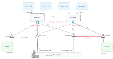
By Mays_Algebary shruthi_nair Establishing redundant network connectivity is vital to ensuring the availability, reliability, and performance of workloads operating in hybrid and cloud environments. Proper planning and implementation of network redundancy are key to achieving high availability and sustaining operational continuity. This article focuses on network redundancy in multi-region architecture. For details on single-region design, refer to this blog. The diagram below illustrates a common network design pattern for multi-region deployments, using either a Hub-and-Spoke or Azure Virtual WAN (vWAN) topology, and serves as the baseline for establishing redundant connectivity throughout this article. In each region, the Hub or Virtual Hub (VHub) extends Azure connectivity to Azure VMware Solution (AVS) via an ExpressRoute circuit. The regional Hub/VHub is connected to on-premises environments by cross-connecting (bowtie) both local and remote ExpressRoute circuits, ensuring redundancy. The concept of weight, used to influence traffic routing preferences, will be discussed in the next section. The diagram below illustrates the traffic flow when both circuits are up and running. Design Considerations If a region loses its local ExpressRoute connection, AVS in that region will lose connectivity to the on-premises environment. However, VNets will still retain connectivity to on-premises via the remote region’s ExpressRoute circuit. The solutions discussed in this article aim to ensure redundancy for both AVS and VNets. Looking at the diagram above, you might wonder: why do we need to set weights at all, and why do the AVS-ER connections (1b/2b) use the same weight as the primary on-premises connections (1a/2a)? Weight is used to influence routing decisions and ensure optimal traffic flow. In this scenario, both ExpressRoute circuits, ER1-EastUS and ER2-WestUS, advertise the same prefixes to the Azure ExpressRoute gateway. As a result, traffic from the VNet to on-premises would be ECMPed across both circuits. To avoid suboptimal routing and ensure that traffic from the VNets prefers the local ExpressRoute circuit, a higher weight is assigned to the local path. It’s also critical that the ExpressRoute gateway connection to on-premises (1a/2a) and to AVS (1b/2b), is assigned the same weight. Otherwise, traffic from the VNet to AVS will follow a less efficient route as AVS routes are also learned over ER1-EastUS via Global Reach. For instance, VNets in EastUS will connect to AVS EUS through ER1-EastUS circuit via Global Reach (as shown by the blue dotted line), instead of using the direct local path (orange line). This suboptimal routing is illustrated in the below diagram. Now let us see what solutions we can have to achieve redundant connectivity. The following solutions will apply to both Hub-and-Spoke and vWAN topology unless noted otherwise. Note: The diagrams in the upcoming solutions will focus only on illustrating the failover traffic flow. Solution1: Network Redundancy via ExpressRoute in Different Peering Location In the solution, deploy an additional ExpressRoute circuit in a different peering location within the same metro area (e.g., ER2–PeeringLocation2), and enable Global Reach between this new circuit and the existing AVS ExpressRoute (e.g., AVS-ER1). If you intend to use this second circuit as a failover path, apply prepends to the on-premises prefixes advertised over it. Alternatively, if you want to use it as an active-active redundant path, do not prepend routes, in this case, both AVS and Azure VNets will ECMP to distribute traffic across both circuits (e.g., ER1–EastUS and ER–PeeringLocation2) when both are available. Note: Compared to the Standard Topology, this design removes both the ExpressRoute cross-connect (bowtie) and weight settings. When adding a second circuit in the same metro, there's no benefit in keeping them, otherwise traffic from the Azure VNet will prefer the local AVS circuit (AVS-ER1/AVS-ER2) to reach on-premises due to the higher weight, as on-premises routes are also learned over AVS circuit (AVS-ER1/AVS-ER2) via Global Reach. Also, when connecting the new circuit (e.g., ER–Peering Location2), remove all weight settings across the connections. Traffic will follow the optimal path based on BGP prepending on the new circuit, or load-balance (ECMP) if no prepend is applied. Note: Use public ASN to prepend the on-premises prefix as AVS circuit (e.g., AVS-ER) will strip the private ASN toward AVS. Solution Insights Ideal for mission-critical applications, providing predictable throughput and bandwidth for backup. It could be cost prohibitive depending on the bandwidth of the second circuit. Solution2: Network Redundancy via ExpressRoute Direct In this solution, ExpressRoute Direct is used to provision multiple circuits from a single port pair in each region, for example, ER2-WestUS and ER4-WestUS are created from the same port pair. This allows you to dedicate one circuit for local traffic and another for failover to a remote region. To ensure optimal routing, prepend the on-premises prefixes using public ASN on the newly created circuit (e.g., ER3-EastUS and ER4-WestUS). Remove all weight settings across the connections; traffic will follow the optimal path based on BGP prepending on the new circuit. For instance, if ER1-EastUS becomes unavailable, traffic from AVS and VNets in the EastUS region will automatically route through ER4-WestUS circuit, ensuring continuity. Note: Compared to the Standard Topology, this design connects the newly created ExpressRoute circuits (e.g., ER3-EastUS/ER4-WestUS) to the remote region of ExpressRoute gateway (black dotted lines) instead of having the bowtie to the primary circuits (e.g., ER1-EastUS/ER2-WestUS). Solution Insights Easy to implement if you have ExpressRoute Direct. ExpressRoute Direct supports over- provisioning where you can create logical ExpressRoute circuits on top of your existing ExpressRoute Direct resource of 10-Gbps or 100-Gbps up to the subscribed Bandwidth of 20 Gbps or 200 Gbps. For example, you can create two 10-Gbps ExpressRoute circuits within a single 10-Gbps ExpressRoute Direct resource (port pair). Ideal for mission-critical applications, providing predictable throughput and bandwidth for backup. Solution3: Network Redundancy via ExpressRoute Metro Metro ExpressRoute is a new configuration that enables dual-homed connectivity to two different peering locations within the same city. This setup enhances resiliency by allowing traffic to continue flowing even if one peering location goes down, using the same circuit. Solution Insights Higher Resiliency: Provides increased reliability with a single circuit. Limited regional availability: Currently available in select regions, with more being added over time. Cost-effective: Offers redundancy without significantly increasing costs. Solution4: Deploy VPN as a Backup to ExpressRoute This solution mirrors solution 1 for a single region but extends it to multiple regions. In this approach, a VPN serves as the backup path for each region in the event of an ExpressRoute failure. In a Hub-and-Spoke topology, a backup path to and from AVS can be established by deploying Azure Route Server (ARS) in the hub VNet. ARS enables seamless transit routing between ExpressRoute and the VPN gateway. In vWAN topology, ARS is not required; the vHub's built-in routing service automatically provides transitive routing between the VPN gateway and ExpressRoute. In this design, you should not cross-connect ExpressRoute circuits (e.g., ER1-EastUS and ER2-WestUS) to the ExpressRoute gateways in the Hub VNets (e.g., Hub-EUS or Hub-WUS). Doing so will lead to routing issues, where the Hub VNet only programs the on-premises routes learned via ExpressRoute. For instance, in the EastUS region, if the primary circuit (ER1-EastUS) goes down, Hub-EUS will receive on-premises routes from both the VPN tunnel and the remote ER2-WestUS circuit. However, it will prefer and program only the ExpressRoute-learned routes from ER2-WestUS circuit. Since ExpressRoute gateways do not support route transitivity between circuits, AVS connected via AVS-ER will not receive the on-premises prefixes, resulting in routing failures. Note: In vWAN topology, to ensure optimal route convergence when failing back to ExpressRoute, you should prepend the prefixes advertised from on-premises over the VPN. Without route prepending, VNets may continue to use the VPN as the primary path to on-premises. If prepend is not an option, you can trigger the failover manually by bouncing the VPN tunnel. Solution Insights Cost-effective and straightforward to deploy. Increased Latency: The VPN tunnel over the internet adds latency due to encryption overhead. Bandwidth Considerations: Multiple VPN tunnels might be needed to achieve bandwidth comparable to a high-capacity ExpressRoute circuit (e.g., over 1G). For details on VPN gateway SKU and tunnel throughput, refer to this link. As you can't cross connect ExpressRoute circuits, VNets will utilize the VPN for failover instead of leveraging remote region ExpressRoute circuit. Solution5: Network Redundancy-Multiple On-Premises (split-prefix) In many scenarios, customers advertise the same prefix from multiple on-premises locations to Azure. However, if the customer can split prefixes across different on-premises sites, it simplifies the implementation of failover strategy using existing ExpressRoute circuits. In this design, each on-premises advertises region-specific prefixes (e.g., 10.10.0.0/16 for EastUS and 10.70.0.0/16 for WestUS), along with a common supernet (e.g., 10.0.0.0/8). Under normal conditions, AVS and VNets in each region use longest prefix match to route traffic efficiently to the appropriate on-premises location. For instance, if ER1-EastUS becomes unavailable, AVS and VNets in EastUS will automatically fail over to ER2-WestUS, routing traffic via the supernet prefix to maintain connectivity. Solution Insights Cost-effective: no additional deployment, using existing ExpressRoute circuits. Advertising specific prefixes over each region might need additional planning. Ideal for mission-critical applications, providing predictable throughput and bandwidth for backup. Solution6: Prioritize Network Redundancy for One Region Over Another If you're operating under budget constraints and can prioritize one region (such as hosting critical workloads in a single location) and want to continue using your existing ExpressRoute setup, this solution could be an ideal fit. In this design, assume AVS in EastUS (AVS-EUS) hosts the critical workloads. To ensure high availability, AVS-ER1 is configured with Global Reach connections to both the local ExpressRoute circuit (ER1-EastUS) and the remote circuit (ER2-WestUS). Make sure to prepend the on-premises prefixes advertised to ER2-WestUS using public ASN to ensure optimal routing (no ECMP) from AVS-EUS over both circuits (ER1-EastUS and ER2-WestUS). On the other hand, AVS in WestUS (AVS-WUS) is connected via Global Reach only to its local region ExpressRoute circuit (ER2-WestUS). If that circuit becomes unavailable, you can establish an on-demand Global Reach connection to ER1-EastUS, either manually or through automation (e.g., a triggered script). This approach introduces temporary downtime until the Global Reach link is established. You might be thinking, why not set up Global Reach between the AVS-WUS circuit and remote region circuits (like connecting AVS-ER2 to ER1-EastUS), just like we did for AVS-EUS? Because it would lead to suboptimal routing. Due to AS path prepending on ER2-WestUS, if both ER1-EastUS and ER2-WestUS are linked to AVS-ER2, traffic would favor the remote ER1-EastUS circuit since it presents a shorter AS path. As a result, traffic would bypass the local ER2-WestUS circuit, causing inefficient routing. That is why for AVS-WUS, it's better to use on-demand Global Reach to ER1-EastUS as a backup path, enabled manually or via automation, only when ER2-WestUS becomes unavailable. Note: VNets will failover via local AVS circuit. E.g., HUB-EUS will route to on-prem through AVS-ER1 and ER2-WestUS via Global Reach Secondary (purple line). Solution Insights Cost-effective Workloads hosted in AVS within the non-critical region will experience downtime if the local region ExpressRoute circuit becomes unavailable, until the on-demand Global Reach connection is established. Conclusion Each solution has its own advantages and considerations, such as cost-effectiveness, ease of implementation, and increased resiliency. By carefully planning and implementing these solutions, organizations can ensure operational continuity and optimal traffic routing in multi-region deployments.3.2KViews7likes0CommentsUnderstanding ExpressRoute private peering to address ExpressRoute resiliency
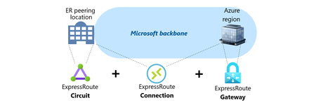
This article provides an overview of Microsoft ExpressRoute, including its various components such as the Circuit, the Gateway and the Connection, and different connectivity models like ExpressRoute Service Provider and ExpressRoute Direct. It also covers the resilience and failure scenarios related to ExpressRoute, including geo-redundancy, Availability Zones, and route advertisement limits. If you're looking to learn more about ExpressRoute and its implementation, this article is a great resource.12KViews7likes3CommentsMicrosoft Azure scales Hollow Core Fiber (HCF) production through outsourced manufacturing
Introduction As cloud and AI workloads surge, the pressure on datacenter (DC), Metro and Wide Area Network (WAN) networks has never been greater. Microsoft is tackling the physical limits of traditional networking head-on. From pioneering research in microLED technologies to deploying Hollow Core Fiber (HCF) at global scale, Microsoft is reimagining connectivity to power the next era of cloud networking. Azure’s HCF journey has been one of relentless innovation, collaboration, and a vision to redefine the physical layer of the cloud. Microsoft’s HCF, based on the proprietary Double Nested Antiresonant Nodeless Fiber (DNANF) design, delivers up to 47% faster data transmission and approximately 33% lower latency compared to conventional Single Mode Fiber (SMF), bringing significant advantages to the network that powers Azure. Today, Microsoft is announcing a major milestone: the industrial scale-up of HCF production, powered by new strategic manufacturing collaborations with Corning Incorporated (Corning) and Heraeus Covantics (Heraeus). These collaborations will enable Azure to increase the global fiber production of HCF to meet the demands of the growing network infrastructure, advancing the performance and reliability customers expect for cloud and AI workloads. Real-world benefits for Azure customers Since 2023, Microsoft has deployed HCF across multiple Azure regions, with production links meeting performance and reliability targets. As manufacturing scales, Azure plans to expand deployment of the full end-to-end HCF network solution to help increase capacity, resiliency, and speed for customers, with the potential to set new benchmarks for latency and efficiency in fiber infrastructure. Why it matters Microsoft’s proprietary HCF design brings the following improvements for Azure customers: Increased data transmission speeds with up to 33% lower latency. Enhanced signal performance that improves data transmission quality for customers. Improved optical efficiency resulting in higher bandwidth rates compared to conventional fiber. How Microsoft is making it possible To operationalize HCF across Azure with production grade performance, Microsoft is: Deploying a standardized HCF solution with end-to-end systems and components for operational efficiency, streamlined network management, and reliable connectivity across Azure’s infrastructure. Ensuring interoperability with standard SMF environments, enabling seamless integration with existing optical infrastructure in the network for faster deployment and scalable growth. Creating a multinational production supply chain to scale next generation fiber production, ensuring the volumes and speed to market needed for widespread HCF deployment across the Azure network. Scaling up and out With Corning and Heraeus as Microsoft’s first HCF manufacturing collaborators, Azure plans to accelerate deployment to meet surging demand for high-performance connectivity. These collaborations underscore Microsoft’s commitment to enhancing its global infrastructure and delivering a reliable customer experience. They also reinforce Azure’s continued investment in deploying HCF, with a vision for this technology to potentially set the global benchmark for high-capacity fiber innovation. “This milestone marks a new chapter in reimagining the cloud’s physical layer. Our collaborations with Corning and Heraeus establish a resilient, global HCF supply chain so Azure can deliver a standardized, world-class customer experience with ultra-low latency and high reliability for modern AI and cloud workloads.” - Jamie Gaudette, Partner Cloud Network Engineering Manager at Microsoft To scale HCF production, Microsoft will utilize Corning’s established U.S. facilities, while Heraeus will produce out of its sites in both Europe and the U.S. "Corning is excited to expand our longtime collaboration with Microsoft, leveraging Corning’s fiber and cable manufacturing facilities in North Carolina to accelerate the production of Microsoft's Hollow Core Fiber. This collaboration not only strengthens our existing relationship but also underscores our commitment to advancing U.S. leadership in AI innovation and infrastructure. By working closely with Microsoft, we are poised to deliver solutions that meet the demands of AI workloads, setting new benchmarks for speed and efficiency in fiber infrastructure." - Mike O'Day, Senior Vice President and General Manager, Corning Optical Communications “We started our work on HCF a decade ago, teamed up with the Optoelectronics Research Centre (ORC) at the University of Southampton and then with Lumenisity prior to its acquisition. Now, we are excited to continue working with Microsoft on shaping the datacom industry. With leading solutions in glass, tube, preform, and fiber manufacturing, we are ready to scale this disruptive HCF technology to significant volumes. We’ll leverage our proven track record of taking glass and fiber innovations from the lab to widespread adoption, just as we did in the telecom industry, where approximately 2 billion kilometers of fiber are made using Heraeus products.” - Dr. Jan Vydra, Executive Vice President Fiber Optics, Heraeus Covantics Azure engineers are working alongside Corning and Heraeus to operationalize Microsoft manufacturing process intellectual property (IP), deliver targeted training programs, and drive the yield, metrology, and reliability improvements required for scaled production. The collaborations are foundational to a growing standardized, global ecosystem that supports: Glass preform/tubing supply Fiber production at scale Cable and connectivity for deployment into carrier‑grade environments Building on a foundation of innovation: Microsoft’s HCF program In 2022, Microsoft acquired Lumenisity, a spin‑out from the Optoelectronics Research Centre (ORC) at the University of Southampton, UK. That same year, Microsoft launched the world’s first state‑of‑the‑art HCF fabrication facility in the UK to expand production and drive innovation. This purpose-built site continues to support long‑term HCF research, prototyping, and testing, ensuring that Azure remains at the forefront of HCF technology. Working with industry leaders, Microsoft has developed a proven end‑to‑end ecosystem of components, equipment, and HCF‑specific hardware necessary and successfully proven in production deployments and operations. Pushing the boundaries: recent breakthrough research Today, the University of Southampton announced a landmark achievement in optical communications: in collaboration with Azure Fiber researchers, they have demonstrated the lowest signal loss ever recorded for optical fibers (<0.1 dB/km) using research-grade DNANF HCF technology (see figure 4). This breakthrough, detailed in a research paper published in Nature Photonics earlier this month, paves the way for a potential revolution in the field, enabling unprecedented data transmission capacities and longer unamplified spans. ecords at around 1550nm [1] 2002 Nagayama et al. 1 [2] 2025 Sato et al. 2 [3] 2025 research-grade DNANF HCF Petrovich et al. 3 This breakthrough highlights the potential for this technology to transform global internet infrastructure and DC connectivity. Expected benefits include: Faster: Approximately 47% faster, reducing latency, powering real-time AI inference, cloud gaming and other interactive workloads. More capacity: A wider optical spectrum window enabling exponentially greater bandwidth. Future-ready: Lays the groundwork for quantum-safe links, quantum computing infrastructure, advanced sensing, and remote laser delivery. Looking ahead: Unlocking the future of cloud networking The future of cloud networking is being built today! With record-breaking [3] fiber innovations, a rapidly expanding collaborative ecosystem, and the industrialized scale to deliver next-generation performance, Azure continues to evolve to meet the demands for speed, reliability, and connectivity. As we accelerate the deployment of HCF across our global network, we’re not just keeping pace with the demands of AI and cloud, we’re redefining what’s possible. References: [1] Nagayama, K., Kakui, M., Matsui, M., Saitoh, T. & Chigusa, Y. Ultra-low-loss (0.1484 dB/km) pure silica core fibre and extension of transmission distance. Electron. Lett. 38, 1168–1169 (2002). [2] Sato, S., Kawaguchi, Y., Sakuma, H., Haruna, T. & Hasegawa, T. Record low loss optical fiber with 0.1397 dB/km. In Proc. Optical Fiber Communication Conference (OFC) 2024 Tu2E.1 (Optica Publishing Group, 2024). [3] Petrovich, M., Numkam Fokoua, E., Chen, Y., Sakr, H., Isa Adamu, A., Hassan, R., Wu, D., Fatobene Ando, R., Papadimopoulos, A., Sandoghchi, S., Jasion, G., & Poletti, F. Broadband optical fibre with an attenuation lower than 0.1 decibel per kilometre. Nat. Photon. (2025). https://doi.org/10.1038/s41566-025-01747-5 Useful Links: The Deployment of Hollow Core Fiber (HCF) in Azure’s Network How hollow core fiber is accelerating AI | Microsoft Azure Blog Learn more about Microsoft global infrastructure14KViews6likes0CommentsCombining firewall protection and SD-WAN connectivity in Azure virtual WAN
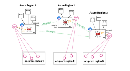
Virtual WAN (vWAN) introduces new security and connectivity features in Azure, including the ability to operate managed third-party firewalls and SD-WAN virtual appliances, integrated natively within a virtual WAN hub (vhub). This article will discuss updated network designs resulting from these integrations and examine how to combine firewall protection and SD-WAN connectivity when using vWAN. The objective is not to delve into the specifics of the security or SD-WAN connectivity solutions, but to provide an overview of the possibilities. Firewall protection in vWAN In a vWAN environment, the firewall solution is deployed either automatically inside the vhub (Routing Intent) or manually in a transit VNet (VM-series deployment). Routing Intent (managed firewall) Routing Intent refers to the concept of implementing a managed firewall solution within the vhub for internet protection or private traffic protection (VNet-to-VNet, Branch-to-VNet, Branch-to-Branch), or both. The firewall could be either an Azure Firewall or a third-party firewall, deployed within the vhub as Network Virtual Appliances or a SaaS solution. A vhub containing a managed firewall is called a secured hub. For an updated list of Routing Intent supported third-party solutions please refer to the following links: managed NVAs SaaS solution Transit VNet (unmanaged firewall) Another way to provide inspection in vWAN is to manually deploy the firewall solution in a spoke of the vhub and to cascade the actual spokes behind that transit firewall VNet (aka indirect spoke model or tiered-VNet design). In this discussion, the primary reasons for choosing unmanaged deployments are: either the firewall solution lacks an integrated vWAN offer, or it has an integrated offer but falls short in horizontal scalability or specific features compared to the VM-based version. For a detailed analysis on the pros and cons of each design please refer to this article. SD-WAN connectivity in vWAN Similar to the firewall deployment options, there are two main methods for extending an SDWAN overlay into an Azure vWAN environment: a managed deployment within the vhub, or a standard VM-series deployment in a spoke of the vhub. More options here. SD-WAN in vWAN deployment (managed) In this scenario, a pair of virtual SD-WAN appliances are automatically deployed and integrated in the vhub using dynamic routing (BGP) with the vhub router. Deployment and management processes are streamlined as these appliances are seamlessly provisioned in Azure and set up for a simple import into the partner portal (SD-WAN orchestrator). For an updated list of supported SDWAN partners please refer to this link. For more information on SD-WAN in vWAN deployments please refer to this article. VM-series deployment (unmanaged) This solution requires manual deployment of the virtual SD-WAN appliances in a spoke of the vhub. The underlying VMs and the horizontal scaling are managed by the customer. Dynamic route exchange with the vWAN environment is achieved leveraging BGP peering with the vhub. Alternatively, and depending on the complexity of your addressing plan, static routing may also be possible. Firewall protection and SD-WAN in vWAN THE CHALLENGE! Currently, it is only possible to chain managed third-party SD-WAN connectivity with Azure Firewall in the same vhub, or to use dual-role SD-WAN connectivity and security appliances. Routing Intent provided by third-party firewalls combined with another managed SD-WAN solution inside the same vhub is not yet supported. But how can firewall protection and SD-WAN connectivity be integrated together within vWAN? Solution 1: Routing Intent with Azure Firewall and managed SD-WAN (same vhub) Firewall solution: managed. SD-WAN solution: managed. This design is only compatible with Routing Intent using Azure Firewall, as it is the sole firewall solution that can be combined with a managed SD-WAN in vWAN deployment in that same vhub. With the private traffic protection policy enabled in Routing Intent, all East-West flows (VNet-to-VNet, Branch-to-VNet, Branch-to-Branch) are inspected. Solution 2: Routing Intent with a third-party firewall and managed SD-WAN (2 vhubs) Firewall solution: managed. SD-WAN solution: managed. To have both a third-party firewall managed solution in vWAN and an SD-WAN managed solution in vWAN in the same region, the only option is to have a vhub dedicated to the security solution deployment and another vhub dedicated to the SD-WAN solution deployment. In each region, spoke VNets are connected to the secured vhub, while SD-WAN branches are connected to the vhub containing the SD-WAN deployment. In this design, Routing Intent private traffic protection provides VNet-to-VNet and Branch-to-VNet inspection. However, Branch-to-Branch traffic will not be inspected. Solution 3: Routing Intent and SD-WAN spoke VNet (same vhub) Firewall solution: managed. SD-WAN solution: unmanaged. This design is compatible with any Routing Intent supported firewall solution (Azure Firewall or third-party) and with any SD-WAN solution. With Routing Intent private traffic protection enabled, all East-West flows (VNet-to-VNet, Branch-to-VNet, Branch-to-Branch) are inspected. Solution 4: Transit firewall VNet and managed SDWAN (same vhub) Firewall solution: unmanaged. SD-WAN solution: managed. This design utilizes the indirect spoke model, enabling the deployment of managed SD-WAN in vWAN appliances. This design provides VNet-to-VNet and Branch-to-VNet inspection. But because the firewall solution is not hosted in the hub, Branch-to-Branch traffic will not be inspected. Solution 5 - Transit firewall VNet and SD-WAN spoke VNet (same vhub) Firewall solution: unmanaged. SD-WAN solution: unmanaged. This design integrates both the security and the SD-WAN connectivity as unmanaged solutions, placing the responsibility for deploying and managing the firewall and the SD-WAN hub on the customer. Just like in solution #4, only VNet-to-VNet and Branch-to-VNet traffic is inspected. Conclusion Although it is currently not possible to combine a managed third-party firewall solution with a managed SDWAN deployment within the same vhub, numerous design options are still available to meet various needs, whether managed or unmanaged approaches are preferred.6KViews6likes2CommentsAzure Front Door: Resiliency Series – Part 2: Faster recovery (RTO)
Abhishek Tiwari, Vice President of Engineering, Azure Networking Amit Srivastava, Partner Director of PM, Azure Networking Varun Chawla, Partner Director of Engineering, Azure Networking Karthik Uthaman, Principal Engineer, Azure Networking In Part 1 of this blog series, we outlined our four‑pillar strategy for resiliency in Azure Front Door: configuration resiliency, data plane resiliency, tenant isolation, and accelerated Recovery Time Objective (RTO). Together, these pillars help Azure Front Door remain continuously available and resilient at global scale. Part 1 focused on the first two pillars: configuration and data plane resiliency. Our goal is to make configuration propagation safer, so incompatible changes never escape pre‑production environments. We discussed how incompatible configurations are blocked early, and how data plane resiliency ensures the system continues serving traffic from a last‑known‑good (LKG) configuration even if a bad change manages to propagate. We also introduced ‘Food Taster’, a dedicated sacrificial process running in each edge server’s data plane, that pretests every configuration change in isolation, before it ever reaches the live data plane. In this post, we turn to the recovery pillar. We describe how we have made key enhancements to the Azure Front Door recovery path so the system can return to full operation in a predictable and bounded timeframe. For a global service like Azure Front Door, serving hundreds of thousands of tenants across 210+ edge sites worldwide, we set an explicit target: to be able to recover any edge site – or all edge sites – within approximately 10 minutes, even in worst‑case scenarios. In typical data plane crash scenarios, we expect recovery in under a second. Repair status The first blog post in this series mentioned the two Azure Front Door incidents from October 2025 – learn more by watching our Azure Incident Retrospective session recordings for the October 9 th incident and/or the October 29 th incident. Before diving into our platform investments for improving our Recovery Time Objectives (RTO), we wanted to provide a quick update on the overall repair items from these incidents. We are pleased to report that the work on configuration propagation and data plane resiliency is now complete and fully deployed across the platform (in the table below, “Completed” means broadly deployed in production). With this, we have reduced configuration propagation latency from ~45 minutes to ~20 minutes. We anticipate reducing this even further – to ~15 minutes by the end of April 2026, while ensuring that platform stability remains our top priority. Learning category Goal Repairs Status Safe customer configuration deployment Incompatible configuration never propagates beyond ‘EUAP or canary regions’ Control plane and data plane defect fixes Forced synchronous configuration processing Additional stages with extended bake time Early detection of crash state Completed Data plane resiliency Configuration processing cannot impact data plane availability Manage data-plane lifecycle to prevent outages caused by configuration-processing defects. Completed Isolated work-process in every data plane server to process and load the configuration. Completed 100% Azure Front Door resiliency posture for Microsoft internal services Microsoft operates an isolated, independent Active/Active fleet with automatic failover for critical Azure services Phase 1: Onboarded critical services batch impacted on Oct 29 th outage running on a day old configuration Completed Phase 2: Automation & hardening of operations, auto-failover and self-management of Azure Front Door onboarding for additional services March 2026 Recovery improvements Data plane crash recovery in under 10 minutes Data plane boot-up time optimized via local cache (~1 hour) Completed Accelerate recovery time < 10 minutes April 2026 Tenant isolation No configuration or traffic regression can impact other tenants Micro cellular Azure Front Door with ingress layered shards June 2026 Why recovery at edge scale is deceptively hard To understand why recovery took as long as it did, it helps to first understand how the Azure Front Door data plane processes configuration. Azure Front Door operates in 210+ edge sites with multiple servers per site. The data plane of each edge server hosts multiple processes. A master process orchestrates the lifecycle of multiple worker processes, that serve customer traffic. A separate configuration translator process runs alongside the data plane processes, and is responsible for converting customer configuration bundles from the control plane into optimized binary FlatBuffer files. This translation step, covering hundreds of thousands of tenants, represents hours of cumulative computation. A per edge server cache is kept locally at each server level – to enable a fast recovery of the data plane, if needed. Once the configuration translator process produces these FlatBuffer files, each worker processes them independently and memory-maps them for zero-copy access. Configuration updates flow through a two-phase commit: new FlatBuffers are first loaded into a staging area and validated, then atomically swapped into production maps. In-flight requests continue using the old configuration, until the last request referencing them completes. The data process recovery is designed to be resilient to different failure modes. A failure or crash at the worker process level has a typical recovery time of less than one second. Since each server has multiple such worker processes which serve customer traffic, this type of crash has no impact on the data plane. In the case of a master process crash, the system automatically tries to recover using the local cache. When the local cache is reused, the system is able to recover quickly – in approximately 60 minutes – since most of the configurations in the cache were already loaded into the data plane before the crash. However, in certain cases if the cache becomes unavailable or must be invalidated because of corruption, the recovery time increases significantly. During the October 29 th incident, a data plane crash triggered a complete recovery sequence that took approximately 4.5 hours. This was not because restarting a process is slow, it is because a defect in the recovery process invalidated the local cache, which meant that “restart” meant rebuilding everything from scratch. The configuration translator process then had to re-fetch and re-translate every one of the hundreds of thousands of customer configurations, before workers could memory-map them and begin serving traffic. This experience has crystallized three fundamental learnings related to our recovery path: Expensive rework: A subset of crashes discarded all previously translated FlatBuffer artifacts, forcing the configuration translator process to repeat hours of conversion work that had already been validated and stored. High restart costs: Every worker on every node had to wait for the configuration translator process to complete the full translation, before it could memory-map any configuration and begin serving requests. Unbounded recovery time: Recovery time grew linearly with total tenant footprint rather than with active traffic, creating a ‘scale penalty’ as more tenants onboarded to the system. Separately and together, the insight was clear: recovery must stop being proportional to the total configuration size. Persisting ‘validated configurations’ across restarts One of the key recovery improvements was strengthening how validated customer configurations are cached and reused across failures, rather than rebuilding configuration states from scratch during recovery. Azure Front Door already cached customer configurations on host‑mounted storage prior to the October incident. The platform enhancements post outage focused on making the local configuration cache resilient to crashes, partial failures, and bad tenant inputs. Our goal was to ensure that recovery behavior is dominated by serving traffic safely, not by reconstructing configuration state. This led us to two explicit design goals… Design goals No category of crash should invalidate the configuration cache: Configuration cache invalidation must never be the default response to failures. Whether the failure is a worker crash, master crash, data plane restart, or coordinated recovery action, previously validated customer configurations should remain usable—unless there is a proven reason to discard it. Bad tenant configuration must not poison the entire cache: A single faulty or incompatible tenant configuration should result in targeted eviction of that tenant’s configuration only—not wholesale cache invalidation across all tenants. Platform enhancements Previously, customer configurations persisted to host‑mounted storage, but certain failure paths treated the cache as unsafe and invalidated it entirely. In those cases, recovery implicitly meant reloading and reprocessing configuration for hundreds of thousands of tenants before traffic could resume, even though the vast majority of cached data was still valid. We changed the recovery model to avoid invalidating customer configurations, with strict scoping around when and how cached entries are discarded: Cached configurations are no longer invalidated based on crash type. Failures are assumed to be orthogonal to configuration correctness unless explicitly proven otherwise. Cache eviction is granular and tenant‑scoped. If a cached configuration fails validation or load checks, only that tenant’s configuration is discarded and reloaded. All other tenant configurations remain available. This ensures that recovery does not regress into a fleet‑wide rebuild due to localized or unrelated faults. Safety and correctness Durability is paired with strong correctness controls, to prevent unsafe configurations from being served: Per‑tenant validation on load: Each cached tenant configuration is validated during the ‘load and verification’ phase, before being promoted for traffic serving. Therefore, failures are contained to that tenant. Targeted re‑translation: When validation fails, only the affected tenant’s configuration is reloaded or reprocessed. Therefore, the cache for other tenants is left untouched. Operational escape hatch: Operators retain the ability to explicitly instruct a clean rebuild of the configuration cache (with proper authorization), preserving control without compromising the default fast‑recovery path. Resulting behavior With these changes, recovery behavior now aligns with real‑world traffic patterns - configuration defects impact tenants locally and predictably, rather than globally. The system now prefers isolated tenant impact, and continued service using last-known-good over aggressive invalidation, both of which are critical for predictable recovery at the scale of Azure Front Door. Making recovery scale with active traffic, not total tenants Reusing configuration cache solves the problem of rebuilding configuration in its entirety, but even with a warm cache, the original startup path had a second bottleneck: eagerly loading a large volume of tenant configurations into memory before serving any traffic. At our scale, memory-mapping, parsing hundreds of thousands of FlatBuffers, constructing internal lookup maps, adding Transport Layer Security (TLS) certificates and configuration blocks for each tenant, collectively added almost an hour to startup time. This was the case even when a majority of those tenants had no active traffic at that moment. We addressed this by fundamentally changing when configuration is loaded into workers. Rather than eagerly loading most of the tenants at startup across all edge locations, Azure Front Door now uses an Machine Learning (ML)-optimized lazy loading model. In the new architecture, instead of loading a large number of tenant configurations, we only load a small subset of tenants that are known to be historically active in a given site, we call this the “warm tenants” list. The warm tenants list per edge site is created through a sophisticated traffic analysis pipeline that leverages ML. However, loading the warm tenants is not good enough, because when a request arrives and we don’t have the configuration in memory, we need to know two things. Firstly, is this a request from a real Azure Front Door tenant – and, if it is, where can I find the configuration? To answer these questions, each worker maintains a hostmap that tracks the state of each tenant’s configuration. This hostmap is constructed during startup, as we process each tenant configuration – if the tenant is in the warm list, we will process and load their configuration fully; if not, then we will just add an entry into the hostmap where all their domain names are mapped to the configuration path location. When a request arrives for one of these tenants, the worker loads and validates that tenant’s configuration on demand, and immediately begins serving traffic. This allows a node to start serving its busiest tenants within a few minutes of startup, while additional tenants are loaded incrementally only when traffic actually arrives—allowing the system to progressively absorb cold tenants as demand increases. The effect on recovery is transformative. Instead of recovery time scaling with the total number of tenants configured on a server, it scales with the number of tenants actively receiving traffic. In practice, even at our busiest edge sites, the active tenant set is a small fraction of the total. Just as importantly, this modified form of lazy loading provides a natural failure isolation boundary. Most Edge sites won’t ever load a faulty configuration of an inactive tenant. When a request for an inactive tenant with an incompatible configuration arrives, impact is contained to a single worker. The configuration load architecture now prefers serving as many customers as quickly as possible, rather than waiting until everything is ready before serving anyone. The above changes are slated to complete in April 2026 and will bring our RTO from the current ~1 hour to under 10 minutes – for complete recovery from a worst case scenario. Continuous validation through Game Days A critical element of our recovery confidence comes from GameDay fault-injection testing. We don’t simply design recovery mechanisms and assume they work—we break the system deliberately and observe how it responds. Since late 2025, we have conducted recurring GameDay drills that simulate the exact failure scenarios we are defending against: Food Taster crash scenarios: Injecting deliberately faulty tenant configurations, to verify that they are caught and isolated with zero impact on live traffic. In our January 2026 GameDay, the Food Taster process crashed as expected, the system halted the update within approximately 5 seconds, and no customer traffic was affected. Master process crash scenarios: Triggering master process crashes across test environments to verify that workers continue serving traffic, that the Local Config Shield engages within 10 seconds, and that the coordinated recovery tool restores full operation within the expected timeframe. Multi-region failure drills: Simulating simultaneous failures across multiple regions to validate that global Config Shield mechanisms engage correctly, and that recovery procedures scale without requiring manual per-region intervention. Fallback test drills for critical Azure services running behind Azure Front Door: In our February 2026 GameDay, we simulated the complete unavailability of Azure Front Door, and successfully validated failover for critical Azure services with no impact to traffic. These drills have both surfaced corner cases and built operational confidence. They have transformed recovery from a theoretical plan into tested, repeatable muscle memory. As we noted in an internal communication to our team: “Game day testing is a deliberate shift from assuming resilience to actively proving it—turning reliability into an observed and repeatable outcome.” Closing Part 1 of this series emphasized preventing unsafe configurations from reaching the data plane, and data plane resiliency in case an incompatible configuration reaches production. This post has shown that prevention alone is not enough—when failures do occur, recovery must be fast, predictable, and bounded. By ensuring that the FlatBuffer cache is never invalidated, by loading only active tenants, and by building safe coordinated recovery tooling, we have transformed failure handling from a fleet-wide crisis into a controlled operation. These recovery investments work in concert with the prevention mechanisms described in Part 1. Together, they ensure that the path from incident detection to full service restoration is measured in minutes, with customer traffic protected at every step. In the next post of this series, we will cover the third pillar of our resiliency strategy: tenant isolation—how micro-cellular architecture and ingress-layered sharding can reduce the blast radius of any failure to a small subset, ensuring that one customer’s configuration or traffic anomaly never becomes everyone’s problem. We deeply value our customers’ trust in Azure Front Door. We are committed to transparently sharing our progress on these resiliency investments, and to exceed expectations for safety, reliability, and operational readiness.3KViews5likes0CommentsAzure Virtual Network Manager + Azure Virtual WAN
Azure continues to expand its networking capabilities, with Azure Virtual Network Manager and Azure Virtual WAN (vWAN) standing out as two of the most transformative services. When deployed together, they offer the best of both worlds: the operational simplicity of a managed hub architecture combined with the ability for spoke VNets to communicate directly, avoiding additional hub hops and minimizing latency Revisiting the classic hub-and-spoke pattern Element Traditional hub-and-spoke role Hub VNet Centralized network that hosts shared services including firewalls (e.g., Azure Firewall, NVAs), VPN/ExpressRoute gateways, DNS servers, domain controllers, and central route tables for traffic management. Acts as the connectivity and security anchor for all spoke networks. Spoke VNets Host individual application workloads and peer directly to the hub VNet. Traffic flows through the hub for north-south connectivity (to/from on-premises or internet) and cross-spoke communication (east-west traffic between spokes). Benefits • Single enforcement point for security policies and network controls • No duplication of shared services across environments • Simplified routing logic and traffic flow management • Clear network segmentation and isolation between workloads • Cost optimization through centralized resources However, this architecture comes with a trade-off: every spoke-to-spoke packet must route through the hub, introducing additional network hops, increased latency, and potential throughput constraints. How Virtual WAN modernizes that design Virtual WAN replaces a do-it-yourself hub VNet with a fully managed hub service: Managed hubs – Azure owns and operates the hub infrastructure. Automatic route propagation – routes learned once are usable everywhere. Integrated add-ons – Firewalls, VPN, and ExpressRoute ports are first-class citizens. By default, Virtual WAN enables any-to-any routing between spokes. Traffic transits the hub fabric automatically—no configuration required. Why direct spoke mesh? Certain patterns require single-hop connectivity Micro-service meshes that sit in different spokes and exchange chatty RPC calls. Database replication / backups where throughput counts, and hub bandwidth is precious. Dev / Test / Prod spokes that need to sync artifacts quickly yet stay isolated from hub services. Segmentation mandates where a workload must bypass hub inspection for compliance yet still talk to a partner VNet. Benefits Lower latency – the hub detour disappears. Better bandwidth – no hub congestion or firewall throughput cap. Higher resilience – spoke pairs can keep talking even if the hub is under maintenance. The peering explosion problem With pure VNet peering, the math escalates fast: For n spokes you need n × (n-1)/2 links. Ten spokes? 45 peerings. Add four more? Now 91. Each extra peering forces you to: Touch multiple route tables. Update NSG rules to cover the new paths. Repeat every time you add or retire a spoke. Troubleshoot an ever-growing spider web. Where Azure Virtual Network Manager Steps In? Azure Virtual Network Manager introduces Network Groups plus a Mesh connectivity policy: Azure Virtual Network Manager Concept What it gives you Network group A logical container that groups multiple VNets together, allowing you to apply configurations and policies to all members simultaneously Mesh connectivity Automated peering between all VNets in the group, ensuring every member can communicate directly with every other member without manual configuration Declarative config Intent-based approach where you define the desired network state, and Azure Virtual Network Manager handles the implementation and ongoing maintenance Dynamic updates Automatic topology management—when VNets are added to or removed from a group, Azure Virtual Network Manager reconfigures all necessary connections without manual intervention Operational complexity collapses from O(n²) to O(1)—you manage a group, not 100+ individual peerings. A complementary model: Azure Virtual Network Manager mesh inside vWAN Since Azure Virtual Network Manager works on any Azure VNet—including the VNets you already attach to a vWAN hub—you can apply mesh policies on top of your existing managed hub architecture: Spoke VNets join a vWAN hub for branch connectivity, centralized firewalling, or multi-region reach. The same spokes are added to an Azure Virtual Network Manager Network Group with a mesh policy. Azure Virtual Network Manager builds direct peering links between the spokes, while vWAN continues to advertise and learn routes. Result: All VNets still benefit from vWAN’s global routing and on-premises integration. Latency-critical east-west flows now travel the shortest path—one hop—as if the VNets were traditionally peered. Rather than choosing one over the other, organizations can leverage both vWAN and Azure Virtual Network Manager together, as the combination enhances the strengths of each service. Performance illustration Spoke-to-Spoke Communication with Virtual WAN without Azure Virtual Network Manager mesh: Spoke-to-Spoke Communication with Virtual WAN with Azure Virtual Network Manager mesh: Observability & protection NSG flow logs – granular packet logs on every peered VNet. Azure Virtual Network Manager admin rules – org-wide guardrails that trump local NSGs. Azure Monitor + SIEM – route flow logs to Log Analytics, Sentinel, or third-party SIEM for threat detection. Layered design – hub firewalls inspect north-south traffic; NSGs plus admin rules secure east-west flows. Putting it all together Virtual WAN offers fully managed global connectivity, simplifying the integration of branch offices and on-premises infrastructure into your Azure environment. Azure Virtual Network Manager mesh establishes direct communication paths between spoke VNets, making it ideal for workloads requiring high throughput or minimal latency in east-west traffic patterns. When combined, these services provide architects with granular control over traffic routing. Each flow can be directed through hub services when needed or routed directly between spokes for optimal performance—all without re-architecting your network or creating additional management complexity. By pairing Azure Virtual Network Manager’s group-based mesh with VWAN’s managed hubs, you get the best of both worlds: worldwide reach, centralized security, and single-hop performance where it counts.3.1KViews5likes0CommentsDeploying Third-Party Firewalls in Azure Landing Zones: Design, Configuration, and Best Practices
As enterprises adopt Microsoft Azure for large-scale workloads, securing network traffic becomes a critical part of the platform foundation. Azure’s Well-Architected Framework provides the blueprint for enterprise-scale Landing Zone design and deployments, and while Azure Firewall is a built-in PaaS option, some organizations prefer third-party firewall appliances for familiarity, feature depth, and vendor alignment. This blog explains the basic design patterns, key configurations, and best practices when deploying third-party firewalls (Palo Alto, Fortinet, Check Point, etc.) as part of an Azure Landing Zone. 1. Landing Zone Architecture and Firewall Role The Azure Landing Zone is Microsoft’s recommended enterprise-scale architecture for adopting cloud at scale. It provides a standardized, modular design that organizations can use to deploy and govern workloads consistently across subscriptions and regions. At its core, the Landing Zone follows a hub-and-spoke topology: Hub (Connectivity Subscription): Central place for shared services like DNS, private endpoints, VPN/ExpressRoute gateways, Azure Firewall (or third-party firewall appliances), Bastion, and monitoring agents. Provides consistent security controls and connectivity for all workloads. Firewalls are deployed here to act as the traffic inspection and enforcement point. Spokes (Workload Subscriptions): Application workloads (e.g., SAP, web apps, data platforms) are placed in spoke VNets. Additional specialized spokes may exist for Identity, Shared Services, Security, or Management. These are isolated for governance and compliance, but all connectivity back to other workloads or on-premises routes through the hub. Traffic Flows Through Firewalls North-South Traffic: Inbound connections from the Internet (e.g., customer access to applications). Outbound connections from Azure workloads to Internet services. Hybrid connectivity to on-premises datacenters or other clouds. Routed through the external firewall set for inspection and policy enforcement. East-West Traffic: Lateral traffic between spokes (e.g., Application VNet to Database VNet). Communication across environments like Dev → Test → Prod (if allowed). Routed through an internal firewall set to apply segmentation, zero-trust principles, and prevent lateral movement of threats. Why Firewalls Matter in the Landing Zone While Azure provides NSGs (Network Security Groups) and Route Tables for basic packet filtering and routing, these are not sufficient for advanced security scenarios. Firewalls add: Deep packet inspection (DPI) and application-level filtering. Intrusion Detection/Prevention (IDS/IPS) capabilities. Centralized policy management across multiple spokes. Segmentation of workloads to reduce blast radius of potential attacks. Consistent enforcement of enterprise security baselines across hybrid and multi-cloud. Organizations May Choose Depending on security needs, cost tolerance, and operational complexity, organizations typically adopt one of two models for third party firewalls: Two sets of firewalls One set dedicated for north-south traffic (external to Azure). Another set for east-west traffic (between VNets and spokes). Provides the highest security granularity, but comes with higher cost and management overhead. Single set of firewalls A consolidated deployment where the same firewall cluster handles both east-west and north-south traffic. Simpler and more cost-effective, but may introduce complexity in routing and policy segregation. This design choice is usually made during Landing Zone design, balancing security requirements, budget, and operational maturity. 2. Why Choose Third-Party Firewalls Over Azure Firewall? While Azure Firewall provides simplicity as a managed service, customers often choose third-party solutions due to: Advanced features – Deep packet inspection, IDS/IPS, SSL decryption, threat feeds. Vendor familiarity – Network teams trained on Palo Alto, Fortinet, or Check Point. Existing contracts – Enterprise license agreements and support channels. Hybrid alignment – Same vendor firewalls across on-premises and Azure. Azure Firewall is a fully managed PaaS service, ideal for customers who want a simple, cloud-native solution without worrying about underlying infrastructure. However, many enterprises continue to choose third-party firewall appliances (Palo Alto, Fortinet, Check Point, etc.) when implementing their Landing Zones. The decision usually depends on capabilities, familiarity, and enterprise strategy. Key Reasons to Choose Third-Party Firewalls Feature Depth and Advanced Security Third-party vendors offer advanced capabilities such as: Deep Packet Inspection (DPI) for application-aware filtering. Intrusion Detection and Prevention (IDS/IPS). SSL/TLS decryption and inspection. Advanced threat feeds, malware protection, sandboxing, and botnet detection. While Azure Firewall continues to evolve, these vendors have a longer track record in advanced threat protection. Operational Familiarity and Skills Network and security teams often have years of experience managing Palo Alto, Fortinet, or Check Point appliances on-premises. Adopting the same technology in Azure reduces the learning curve and ensures faster troubleshooting, smoother operations, and reuse of existing playbooks. Integration with Existing Security Ecosystem Many organizations already use vendor-specific management platforms (e.g., Panorama for Palo Alto, FortiManager for Fortinet, or SmartConsole for Check Point). Extending the same tools into Azure allows centralized management of policies across on-premises and cloud, ensuring consistent enforcement. Compliance and Regulatory Requirements Certain industries (finance, healthcare, government) require proven, certified firewall vendors for security compliance. Customers may already have third-party solutions validated by auditors and prefer extending those to Azure for consistency. Hybrid and Multi-Cloud Alignment Many enterprises run a hybrid model, with workloads split across on-premises, Azure, AWS, or GCP. Third-party firewalls provide a common security layer across environments, simplifying multi-cloud operations and governance. Customization and Flexibility Unlike Azure Firewall, which is a managed service with limited backend visibility, third-party firewalls give admins full control over operating systems, patching, advanced routing, and custom integrations. This flexibility can be essential when supporting complex or non-standard workloads. Licensing Leverage (BYOL) Enterprises with existing enterprise agreements or volume discounts can bring their own firewall licenses (BYOL) to Azure. This often reduces cost compared to pay-as-you-go Azure Firewall pricing. When Azure Firewall Might Still Be Enough Organizations with simple security needs (basic north-south inspection, FQDN filtering). Cloud-first teams that prefer managed services with minimal infrastructure overhead. Customers who want to avoid manual scaling and VM patching that comes with IaaS appliances. In practice, many large organizations use a hybrid approach: Azure Firewall for lightweight scenarios or specific environments, and third-party firewalls for enterprise workloads that require advanced inspection, vendor alignment, and compliance certifications. 3. Deployment Models in Azure Third-party firewalls in Azure are primarily IaaS-based appliances deployed as virtual machines (VMs). Leading vendors publish Azure Marketplace images and ARM/Bicep templates, enabling rapid, repeatable deployments across multiple environments. These firewalls allow organizations to enforce advanced network security policies, perform deep packet inspection, and integrate with Azure-native services such as Virtual Network (VNet) peering, Azure Monitor, and Azure Sentinel. Note: Some vendors now also release PaaS versions of their firewalls, offering managed firewall services with simplified operations. However, for the purposes of this blog, we will focus mainly on IaaS-based firewall deployments. Common Deployment Modes Active-Active Description: In this mode, multiple firewall VMs operate simultaneously, sharing the traffic load. An Azure Load Balancer distributes inbound and outbound traffic across all active firewall instances. Use Cases: Ideal for environments requiring high throughput, resilience, and near-zero downtime, such as enterprise data centers, multi-region deployments, or mission-critical applications. Considerations: Requires careful route and policy synchronization between firewall instances to ensure consistent traffic handling. Typically involves BGP or user-defined routes (UDRs) for optimal traffic steering. Scaling is easier: additional firewall VMs can be added behind the load balancer to handle traffic spikes. Active-Passive Description: One firewall VM handles all traffic (active), while the secondary VM (passive) stands by for failover. When the active node fails, Azure service principals manage IP reassignment and traffic rerouting. Use Cases: Suitable for environments where simpler management and lower operational complexity are preferred over continuous load balancing. Considerations: Failover may result in a brief downtime, typically measured in seconds to a few minutes. Synchronization between the active and passive nodes ensures firewall policies, sessions, and configurations are mirrored. Recommended for smaller deployments or those with predictable traffic patterns. Network Interfaces (NICs) Third-party firewall VMs often include multiple NICs, each dedicated to a specific type of traffic: Untrust/Public NIC: Connects to the Internet or external networks. Handles inbound/outbound public traffic and enforces perimeter security policies. Trust/Internal NIC: Connects to private VNets or subnets. Manages internal traffic between application tiers and enforces internal segmentation. Management NIC: Dedicated to firewall management traffic. Keeps administration separate from data plane traffic, improving security and reducing performance interference. HA NIC (Active-Passive setups): Facilitates synchronization between active and passive firewall nodes, ensuring session and configuration state is maintained across failovers. This design choice is usually made during Landing Zone design, balancing security requirements, budget, and operational maturity. : NICs of Palo Alto External Firewalls and FortiGate Internal Firewalls in two sets of firewall scenario 4. Key Configuration Considerations When deploying third-party firewalls in Azure, several design and configuration elements play a critical role in ensuring security, performance, and high availability. These considerations should be carefully aligned with organizational security policies, compliance requirements, and operational practices. Routing User-Defined Routes (UDRs): Define UDRs in spoke Virtual Networks to ensure all outbound traffic flows through the firewall, enforcing inspection and security policies before reaching the Internet or other Virtual Networks. Centralized routing helps standardize controls across multiple application Virtual Networks. Depending on the architecture traffic flow design, use appropriate Load Balancer IP as the Next Hop on UDRs of spoke Virtual Networks. Symmetric Routing: Ensure traffic follows symmetric paths (i.e., outbound and inbound flows pass through the same firewall instance). Avoid asymmetric routing, which can cause stateful firewalls to drop return traffic. Leverage BGP with Azure Route Server where supported, to simplify route propagation across hub-and-spoke topologies. : Azure UDR directing all traffic from a Spoke VNET to the Firewall IP Address Policies NAT Rules: Configure DNAT (Destination NAT) rules to publish applications securely to the Internet. Use SNAT (Source NAT) to mask private IPs when workloads access external resources. Security Rules: Define granular allow/deny rules for both north-south traffic (Internet to VNet) and east-west traffic (between Virtual Networks or subnets). Ensure least privilege by only allowing required ports, protocols, and destinations. Segmentation: Apply firewall policies to separate workloads, environments, and tenants (e.g., Production vs. Development). Enforce compliance by isolating workloads subject to regulatory standards (PCI-DSS, HIPAA, GDPR). Application-Aware Policies: Many vendors support Layer 7 inspection, enabling controls based on applications, users, and content (not just IP/port). Integrate with identity providers (Azure AD, LDAP, etc.) for user-based firewall rules. : Example Configuration of NAT Rules on a Palo Alto External Firewall Load Balancers Internal Load Balancer (ILB): Use ILBs for east-west traffic inspection between Virtual Networks or subnets. Ensures that traffic between applications always passes through the firewall, regardless of origin. External Load Balancer (ELB): Use ELBs for north-south traffic, handling Internet ingress and egress. Required in Active-Active firewall clusters to distribute traffic evenly across firewall nodes. Other Configurations: Configure health probes for firewall instances to ensure faulty nodes are automatically bypassed. Validate Floating IP configuration on Load Balancing Rules according to the respective vendor recommendations. Identity Integration Azure Service Principals: In Active-Passive deployments, configure service principals to enable automated IP reassignment during failover. This ensures continuous service availability without manual intervention. Role-Based Access Control (RBAC): Integrate firewall management with Azure RBAC to control who can deploy, manage, or modify firewall configurations. SIEM Integration: Stream logs to Azure Monitor, Sentinel, or third-party SIEMs for auditing, monitoring, and incident response. Licensing Pay-As-You-Go (PAYG): Licenses are bundled into the VM cost when deploying from the Azure Marketplace. Best for short-term projects, PoCs, or variable workloads. Bring Your Own License (BYOL): Enterprises can apply existing contracts and licenses with vendors to Azure deployments. Often more cost-effective for large-scale, long-term deployments. Hybrid Licensing Models: Some vendors support license mobility from on-premises to Azure, reducing duplication of costs. 5. Common Challenges Third-party firewalls in Azure provide strong security controls, but organizations often face practical challenges in day-to-day operations: Misconfiguration Incorrect UDRs, route tables, or NAT rules can cause dropped traffic or bypassed inspection. Asymmetric routing is a frequent issue in hub-and-spoke topologies, leading to session drops in stateful firewalls. Performance Bottlenecks Firewall throughput depends on the VM SKU (CPU, memory, NIC limits). Under-sizing causes latency and packet loss, while over-sizing adds unnecessary cost. Continuous monitoring and vendor sizing guides are essential. Failover Downtime Active-Passive models introduce brief service interruptions while IPs and routes are reassigned. Some sessions may be lost even with state sync, making Active-Active more attractive for mission-critical workloads. Backup & Recovery Azure Backup doesn’t support vendor firewall OS. Configurations must be exported and stored externally (e.g., storage accounts, repos, or vendor management tools). Without proper backups, recovery from failures or misconfigurations can be slow. Azure Platform Limits on Connections Azure imposes a per-VM cap of 250,000 active connections, regardless of what the firewall vendor appliance supports. This means even if an appliance is designed for millions of sessions, it will be constrained by Azure’s networking fabric. Hitting this cap can lead to unexplained traffic drops despite available CPU/memory. The workaround is to scale out horizontally (multiple firewall VMs behind a load balancer) and carefully monitor connection distribution. 6. Best Practices for Third-Party Firewall Deployments To maximize security, reliability, and performance of third-party firewalls in Azure, organizations should follow these best practices: Deploy in Availability Zones: Place firewall instances across different Availability Zones to ensure regional resilience and minimize downtime in case of zone-level failures. Prefer Active-Active for Critical Workloads: Where zero downtime is a requirement, use Active-Active clusters behind an Azure Load Balancer. Active-Passive can be simpler but introduces failover delays. Use Dedicated Subnets for Interfaces: Separate trust, untrust, HA, and management NICs into their own subnets. This enforces segmentation, simplifies route management, and reduces misconfiguration risk. Apply Least Privilege Policies: Always start with a deny-all baseline, then allow only necessary applications, ports, and protocols. Regularly review rules to avoid policy sprawl. Standardize Naming & Tagging: Adopt consistent naming conventions and resource tags for firewalls, subnets, route tables, and policies. This aids troubleshooting, automation, and compliance reporting. Validate End-to-End Traffic Flows: Test both north-south (Internet ↔ VNet) and east-west (VNet ↔ VNet/subnet) flows after deployment. Use tools like Azure Network Watcher and vendor traffic logs to confirm inspection. Plan for Scalability: Monitor throughput, CPU, memory, and session counts to anticipate when scale-out or higher VM SKUs are needed. Some vendors support autoscaling clusters for bursty workloads. Maintain Firmware & Threat Signatures: Regularly update the firewall’s software, patches, and threat intelligence feeds to ensure protection against emerging vulnerabilities and attacks. Automate updates where possible. Conclusion Third-party firewalls remain a core building block in many enterprise Azure Landing Zones. They provide the deep security controls and operational familiarity enterprises need, while Azure provides the scalable infrastructure to host them. By following the hub-and-spoke architecture, carefully planning deployment models, and enforcing best practices for routing, redundancy, monitoring, and backup, organizations can ensure a secure and reliable network foundation in Azure.4.2KViews5likes2CommentsManaged SD-WAN in vWAN: throughput considerations and underlay options
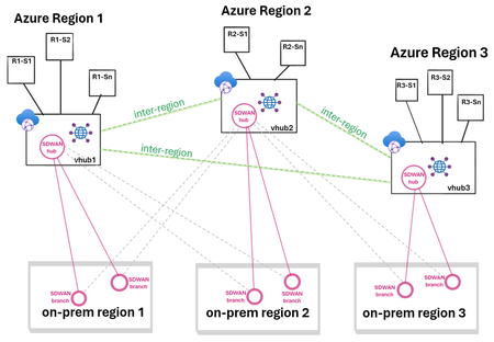
Discover how to simplify large-scale branch connectivity by leveraging the power of SD-WAN and vWAN to create a cloud-oriented network that delivers optimized inter-region performance and resiliency. Get insights on the deployment process for managed SD-WAN in vWAN, as well as on throughput considerations and scaling options. Finally, explore the various underlay options available for managed SD-WAN in vWAN deployments.8.8KViews5likes1CommentAzure Networking Portfolio Consolidation
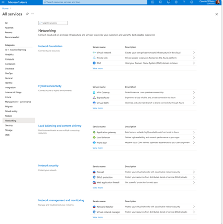
Overview Over the past decade, Azure Networking has expanded rapidly, bringing incredible tools and capabilities to help customers build, connect, and secure their cloud infrastructure. But we've also heard strong feedback: with over 40 different products, it hasn't always been easy to navigate and find the right solution. The complexity often led to confusion, slower onboarding, and missed capabilities. That's why we're excited to introduce a more focused, streamlined, and intuitive experience across Azure.com, the Azure portal, and our documentation pivoting around four core networking scenarios: Network foundations: Network foundations provide the core connectivity for your resources, using Virtual Network, Private Link, and DNS to build the foundation for your Azure network. Try it with this link: Network foundations Hybrid connectivity: Hybrid connectivity securely connects on-premises, private, and public cloud environments, enabling seamless integration, global availability, and end-to-end visibility, presenting major opportunities as organizations advance their cloud transformation. Try it with this link: Hybrid connectivity Load balancing and content delivery: Load balancing and content delivery helps you choose the right option to ensure your applications are fast, reliable, and tailored to your business needs. Try it with this link: Load balancing and content delivery Network security: Securing your environment is just as essential as building and connecting it. The Network Security hub brings together Azure Firewall, DDoS Protection, and Web Application Firewall (WAF) to provide a centralized, unified approach to cloud protection. With unified controls, it helps you manage security more efficiently and strengthen your security posture. Try it with this link: Network security This new structure makes it easier to discover the right networking services and get started with just a few clicks so you can focus more on building, and less on searching. What you’ll notice: Clearer starting points: Azure Networking is now organized around four core scenarios and twelve essential services, reflecting the most common customer needs. Additional services are presented within the context of these scenarios, helping you stay focused and find the right solution without feeling overwhelmed. Simplified choices: We’ve merged overlapping or closely related services to reduce redundancy. That means fewer, more meaningful options that are easier to evaluate and act on. Sunsetting outdated services: To reduce clutter and improve clarity, we’re sunsetting underused offerings such as white-label CDN services and China CDN. These capabilities have been rolled into newer, more robust services, so you can focus on what’s current and supported. What this means for you Faster decision-making: With clearer guidance and fewer overlapping products, it's easier to discover what you need and move forward confidently. More productive sales conversations: With this simplified approach, you’ll get more focused recommendations and less confusion among sellers. Better product experience: This update makes the Azure Networking portfolio more cohesive and consistent, helping you get started quickly, stay aligned with best practices, and unlock more value from day one. The portfolio consolidation initiative is a strategic effort to simplify and enhance the Azure Networking portfolio, ensuring better alignment with customer needs and industry best practices. By focusing on top-line services, combining related products, and retiring outdated offerings, Azure Networking aims to provide a more cohesive and efficient product experience. Azure.com Before: Our original Solution page on Azure.com was disorganized and static, displaying a small portion of services in no discernable order. After: The revised solution page is now dynamic, allowing customers to click deeper into each networking and network security category, displaying the top line services, simplifying the customer experience. Azure Portal Before: With over 40 networking services available, we know it can feel overwhelming to figure out what’s right for you and where to get started. After: To make it easier, we've introduced four streamlined networking hubs each built around a specific scenario to help you quickly identify the services that match your needs. Each offers an overview to set the stage, key services to help you get started, guidance to support decision-making, and a streamlined left-hand navigation for easy access to all services and features. Documentation For documentation, we looked at our current assets as well as created new assets that aligned with the changes in the portal experience. Like Azure.com, we found the old experiences were disorganized and not well aligned. We updated our assets to focus on our top-line networking services, and to call out the pillars. Our belief is these changes will allow our customers to more easily find the relevant and important information they need for their Azure infrastructure. Azure Network Hub Before the updates, we had a hub page organized around different categories and not well laid out. In the updated hub page, we provided relevant links for top-line services within all of the Azure networking scenarios, as well as a section linking to each scenario's hub page. Scenario Hub pages We added scenario hub pages for each of the scenarios. This provides our customers with a central hub for information about the top-line services for each scenario and how to get started. Also, we included common scenarios and use cases for each scenario, along with references for deeper learning across the Azure Architecture Center, Well Architected Framework, and Cloud Adoption Framework libraries. Scenario Overview articles We created new overview articles for each scenario. These articles were designed to provide customers with an introduction to the services included in each scenario, guidance on choosing the right solutions, and an introduction to the new portal experience. Here's the Load balancing and content delivery overview: Documentation links Azure Networking hub page: Azure networking documentation | Microsoft Learn Scenario Hub pages: Azure load balancing and content delivery | Microsoft Learn Azure network foundation documentation | Microsoft Learn Azure hybrid connectivity documentation | Microsoft Learn Azure network security documentation | Microsoft Learn Scenario Overview pages What is load balancing and content delivery? | Microsoft Learn Azure Network Foundation Services Overview | Microsoft Learn What is hybrid connectivity? | Microsoft Learn What is Azure network security? | Microsoft Lea Improving user experience is a journey and in coming months we plan to do more on this. Watch out for more blogs over the next few months for further improvements.3.3KViews4likes0Comments