security
1571 TopicsStrengthening Semiconductor Supply Chain Trust with Microsoft’s Artifact Signing and Transparency
As enterprises expand their use of Confidential Computing in the cloud and in AI infrastructure, the security of the underlying hardware is more critical than ever. Organizations and their customers need confidence not only in the software they deploy, but also in the silicon and firmware executing their most sensitive workloads. AMD and Microsoft are collaborating to demonstrate how signing and transparency can strengthen trust in the semiconductor supply chain. By combining AMD Device Provenance with Microsoft’s Artifact Signing and Signing Transparency, we are exploring how device provenance, signing, and transparency could work together to support independently verifiable hardware evidence. Why Hardware Provenance Needs Transparency Provenance evidence is most useful when it can be independently verified and evaluated alongside related supply chain evidence. Semiconductor manufacturers generate evidence across selected manufacturing and lifecycle stages, which may describe relevant device attributes, manufacturing events, and validation activities. A digitally signed record establishes who issued information and its integrity. Individual signatures alone do not provide a durable and independently verifiable record of the order in which they were issued, whether they were recorded consistently, or whether unexpected activity occurred in the interval. Transparency addresses this gap. Microsoft's Signing Transparency leverages confidential computing to create a verified, tamper-evident record of signing events, allowing customers and auditors to confirm that evidence was recorded and has not been silently changed or been removed. It applies the Zero Trust principle of “trust but Verify” by giving relying parties cryptographic proof they can evaluate directly. Extending Transparency from Software to Silicon Microsoft's Signing Transparency was designed to address software supply chain threats that traditional code signing alone cannot fully prevent. The same principles can be applied to firmware, hardware provenance, and other evidence generated across the physical supply chain. AMD Device Provenance is designed to provide visibility into the manufacturing and lifecycle of data center components. Through our collaboration, AMD and Microsoft are demonstrating how this evidence can be signed, made transparent, and independently validated. This approach provides several important benefits: Transparent provenance: Changes to signed hardware evidence can be detected rather than silently accepted. Independent validation: Customers can independently validate the integrity, signing history, and transparency records associated with provenance evidence while still applying their own trust requirements to the evidence issuer. Stronger accountability: Transparency creates a durable record of signing events, providing evidence that can help identify unexpected patterns or unauthorized signatures. Audit and compliance evidence: Verifiable records may help inform supplier assessments, regulatory inquiries, and internal due diligence. Standards-based portability: Evidence can be validated across organizational boundaries using interoperable IETF specifications, including RFC 9943, An Architecture for Trustworthy and Transparent Digital Supply Chains, RFC 9942, CBOR Object Signing and Encryption Receipts, and RFC 9995, CBOR Object Signing and Encryption Hash Envelope, rather than proprietary trust mechanisms. Together, these capabilities allow relying parties to verify the origin, integrity, registration, and device binding of manufacturer-issued provenance evidence. Learn More at OCP Global Summit At OCP Global Summit 2026, AMD and Microsoft will present a proof-of-concept demonstration that prototypes how these components could operate together. Visit the AMD (#C61) booth to see the demonstration and learn how AMD and Microsoft are advancing semiconductor supply chain security. To dive deeper into the demo details read AMD’s blog Advancing Semiconductor Supply Chain Assurance. Organizations interested in applying Artifact Signing and Signing Transparency to software, firmware, or hardware can also join the Artifact Signing with Signing Transparency preview community to learn more and help shape the future of the service.Security Review for Microsoft Edge version 152
We have reviewed the new settings in Microsoft Edge version 152 and determined that there are no additional security settings that require enforcement. The Microsoft Edge version 151 security baseline continues to be our recommended configuration which can be downloaded from the Microsoft Security Compliance Toolkit. Microsoft Edge version 152 introduced 4 new Computer and User settings; we have included a spreadsheet listing the new settings to make it easier for you to find. Starting with version 152 Microsoft Edge is moving to a more frequent release cycle. To better align with the needs of the enterprise customers, the Microsoft Edge security baseline is expected to align with the Extended Stable Channel, which provides major feature updates on an eight-week cadence while continuing to receive security and quality updates between releases. This approach provides organizations with additional time to evaluate and deploy feature changes while ensuring security protections remain current. Why the change? Security baselines are intended to provide guidance for managing security relevant configuration settings, not to track every feature introduced in a browser release. With the move to a two-week release cadence, publishing baseline updates for every release would increase operational overhead while providing limited security benefit. The Extended Stable cadence offers a more practical balance for enterprise customers by allowing additional time for testing and evaluation, while continuing to receive security and critical fixes between major feature releases. By aligning with Extended Stable, we can update the baselines less frequently and focus on publishing them earlier in the release cycle, giving IT administrators more time to review and plan for upcoming changes. Our goal is to make security baseline adoption more predictable and easier to manage while continuing to provide timely security guidance. As a friendly reminder, all available settings for Microsoft Edge are documented here, and all available settings for Microsoft Edge Update are documented here. Please continue to give us feedback through the Security Baselines Discussion site or this post.1.6KViews0likes6CommentsWindows 11, version 26H2 security baseline
Update: The Windows 11, version 26H2 security baseline has been updated to reflect the general availability of Administrator protection. An updated v2 package is now available, and organizations should review and test the existing Administrator protection configuration as appropriate for their environment. You can download the baseline package from the Microsoft Security Compliance Toolkit, test the recommended configurations in your environment, and customize / implement them as appropriate. Summary of Changes This release includes several changes since the Security baseline for Windows 11, version 25H2 to further strengthen enterprise security and align the baseline with current platform capabilities and industry standards. Security Policy Change Summary Printer\Configure Windows Ready Print driver ranking Configured as “Enabled” to reduce reliance on third-party print drivers in the stack, narrowing the overall print driver attack surface. Internet Explorer\Internet Control Panel\Advanced Page\Turn off encryption support Updated from TLS 1.1 and TLS 1.2 to TLS 1.2 and TLS 1.3 to align with current security standards. User Account Control: Configure type of Admin Approval Mode (updated) Configured as “Admin Approval Mode with Administrator protection” to enable Administrator protection. User Account Control: Behavior of the elevation prompt for administrators running with Administrator protection (updated) Configured as “Prompt for credentials on the secure desktop” to require credential verification for administrative elevation. Windows Ready Print driver ranking Configure Windows Ready Print driver ranking" is the newly added setting under Administrative Templates\Printers to control whether Windows prefers the modern inbox IPP class driver over third-party OEM drivers when installing new printers. We recommend enabling this policy to reduce reliance on third-party print drivers in the stack, narrowing the overall print driver attack surface. Note that driver ranking applies when printers are installed via a connection method that supports IPP, such as USB or network multicast discovery. In those cases, if the printer supports IPP, Windows will install using the class driver even if a vendor V3/V4 driver is available. If the printer doesn't support IPP, or is installed directly as a TCP/IP printer, there's no change in behavior. Encryption Support We have updated the policy "Turn off encryption support" to allow only TLS 1.2 and TLS 1.3. Previous baseline releases permitted TLS 1.1 and TLS 1.2; however, TLS 1.1 is now considered obsolete and is no longer recommended for enterprise environments. This change aligns the security baseline with modern cryptographic standards while maintaining compatibility with widely deployed services that support current TLS versions. Administrator Protection (update) Administrator protection is now generally available. Organizations can enable it through Microsoft Intune or Group Policy. Important: Organizations should review and test their existing configuration and adjust these settings as appropriate for their environment. The security baselines for Windows 11, versions 24H2, 25H2, and 26H2 include settings that enable Administrator protection. The following policies are part of the security baseline: User Account Control: Configure type of Admin Approval Mode User Account Control: Behavior of the elevation prompt for administrators running with Administrator protection An updated v2 package has been published for Windows 11, version 26H2, to reflect this change. Please let us know your thoughts by commenting on this post or through the Security Baseline Community.6.9KViews2likes4Comments
The Microsoft AI and Agent Platform — Securing and Governing Intelligent Agents
In Part 1, we explored the intelligence side of the Microsoft AI and Agent Platform: how agents understand work, reason over trusted context, use models and tools, and operate across experiences such as Microsoft 365 Copilot, Copilot Studio, Microsoft Foundry, Dynamics 365, GitHub, and custom applications. But intelligence is only half the equation. As agents move from answering questions to taking action, the security model changes. Agents can retrieve sensitive data, call APIs, invoke tools, trigger workflows, collaborate with other agents, remember context, and act with delegated or assigned authority. That creates a new enterprise requirement: agents must be not only useful, but also governable, observable, contained, policy-driven, auditable, and aligned with organizational risk boundaries. The core question for enterprise AI is no longer only, “Can the agent reason?” It is also, “Can we trust what it can access, what it can do, how it is governed, and whether we can prove what happened?” That is the focus of Part 2: Trust—showing where security, governance, assurance, isolation, posture management, and security operations apply across the agent lifecycle. The mental model: The left side presents the seven platform layers, while the foundation establishes security across the architecture. On the right, scoped control rails apply targeted governance through Microsoft commercial controls and open-source specifications, with each control operating within its defined scope. Trust is not a feature. It is a platform property. Many early AI security conversations focused narrowly on prompts: prompt injection, jailbreaks, harmful content, and model outputs. Those risks remain important, but agentic systems broaden the attack surface. An enterprise agent is not just a model endpoint. It is a system composed of: User and application interaction channels. Foundation and custom models. Agent orchestration and reasoning. MCP servers, APIs, tools, skills, and connectors. RAG pipelines and enterprise knowledge sources. Short-term and long-term memory. Identity and access controls. Runtime environments, containers, cloud PCs, and networks. Monitoring, audit, compliance, and security operations. Trust must therefore be applied across every layer. A secured agent platform needs controls before the model call, during reasoning, before and after tool execution, at data retrieval time, during output generation, and throughout runtime operation. That is why the Microsoft Security for AI Platform is best understood as an end-to-end security architecture for the AI application and agent lifecycle. The diagram follows the path from interaction channels, through the agent and grounding layers, into build and runtime environments, and finally into security operations. The new security boundary: from applications to agents Traditional application security assumes relatively deterministic behavior: users click buttons, applications call APIs, authorization checks enforce access, and logs record the result. Agentic systems introduce more dynamic behavior. An agent may interpret a goal, decompose it into tasks, choose tools, retrieve context, call APIs, invoke another agent, generate code, operate a browser, or take action through a workflow. That flexibility is where business value comes from, but it also means controls must cover more than static application paths. A secure AI platform must answer several questions: Trust question Why it matters Who is the user and who is the agent? Agents need identity, permissions, ownership, lifecycle, and accountability. What data can the agent retrieve? RAG and grounding can expose overshared or sensitive enterprise data. What tools can the agent use? APIs, MCP servers, connectors, and skills become action surfaces. When does a human need to approve? High-impact actions require explicit approval and evidence. Where does the agent run? Runtime isolation matters when agents execute code, use browsers, or automate legacy apps. What happened? Security teams need traces, logs, detections, investigations, and audit records. How do we govern at scale? Enterprises need policy, posture management, compliance, and lifecycle controls across thousands of agents. Microsoft’s approach is to apply a consistent trust foundation across the same layers that deliver intelligence: interaction channels, AI applications and agents, data and context, build platforms, runtime infrastructure, and security operations. 1. Secure the AI interaction channels Agents enter the enterprise through many channels: Microsoft 365 Copilot, Teams, SharePoint, Office, Dynamics 365, custom portals, APIs, MCP endpoints, web experiences, and developer tools. Each channel has a different risk profile. Microsoft 365 Copilot and business application experiences inherit enterprise identity, compliance, and data protection controls from Microsoft 365, Microsoft Entra, Microsoft Purview, and Microsoft Defender. Custom apps, web apps, and API-driven experiences require the same rigor: authentication, authorization, network controls, input validation, logging, monitoring, and response. For developer tools, GitHub Advanced Security, Microsoft Defender for DevOps, Microsoft Defender for Cloud, and Microsoft Security Copilot help protect the software supply chain behind AI applications. Agent systems often depend on code, prompts, infrastructure-as-code, container images, packages, actions, connectors, and deployment pipelines. Those assets need the same scanning, secret detection, dependency governance, and posture management expected of any production system. For APIs and MCP servers, Azure API Management, Microsoft Defender for APIs, Microsoft Entra, Conditional Access, Private Link, and network controls become especially important. Agent tool use should be explicit, least privileged, monitored, and policy governed. Microsoft Defender for Cloud Apps also plays an important role across interaction channels by helping organizations discover and govern SaaS usage, manage OAuth app risk, apply session controls, and understand shadow AI exposure across the enterprise. 2. Secure the AI application and agent layer The AI application and agent layer is where models, agents, MCP, skills, hooks, RAG, memory, and orchestration come together. This layer sets agent security apart because agents do more than process requests, they reason, make decisions, and take action. Agent harness and the agent loop An agent harness is the runtime scaffolding that turns model reasoning into a stateful agent workflow. It assembles instructions and context, coordinates model and tool calls through the agent loop, maintains session state, and applies configured approvals and observability. Because the harness mediates these interactions, it is a natural integration point for policy controls: Agent Hooks defines standardized interception points, while the Agent Control Specification (ACS) evaluates policy at those points and returns decisions for the host to enforce. The harness is not an execution-isolation boundary; tools and code may run in separate containers, sandboxes, Cloud PCs, or hosted environments that require their own security controls. Models Foundation and custom models should be governed through approved model catalogs, deployment policies, evaluation pipelines, content safety controls, and monitoring. Microsoft Foundry provides a governed environment for model selection, evaluation, deployment, and operations. Model choice should be treated as a policy decision, not an uncontrolled developer preference. Different workloads may require different tradeoffs across cost, latency, quality, data handling, region, safety, and compliance. Enterprises need visibility into which models are used, for which workloads, and under which controls. Azure AI Content Safety, available through Microsoft Foundry capabilities, helps protect AI applications from harmful content, prompt attacks, jailbreak attempts, unsafe outputs, and other content risks. Content safety should be treated as part of the AI control plane, not a bolt-on filter at the edge. Agents Agents need their own lifecycle: discovery, ownership, identity, permissions, classification, monitoring, and retirement. Agent 365 helps organizations discover, inventory, govern, and enforce policies across their agent estate, preventing it from becoming an unmanaged shadow application layer. This matters because agent sprawl can become the next application sprawl. Without inventory and governance, organizations may not know which agents exist, who owns them, what data they access, what tools they can invoke, or whether they are still needed. Microsoft Purview complements this by helping protect and govern the data agents use, including sensitivity labels, data loss prevention, audit, compliance, and data security posture management for AI scenarios. Microsoft Entra provides the identity fabric for users, apps, agents, and workloads, helping ensure that agent actions are tied to explicit identities and least-privilege access. MCP, APIs, tools, and skills The Model Context Protocol and tool-based agent architectures are powerful because they let agents connect to systems of record, business applications, knowledge stores, and automation surfaces. They are also high-value control points. Every tool is effectively a capability grant. A read-only knowledge tool, a refund API, a database query tool, a ticketing connector, a browser automation tool, and a code execution tool carry very different risk. Tool authorization should be granular, contextual, and auditable. Key controls include: Tool allowlisting and approval workflows. Least-privilege API permissions. Strong authentication through Microsoft Entra. Managed identities and workload identities for secretless access. API inspection and protection with Azure API Management and Defender for APIs. Network isolation with Private Link, Azure Firewall, WAF, and DDoS Protection. Runtime isolation with containers, Microsoft eXecution Container (MXC), Windows 365 for Agents, and confidential computing where needed. Monitoring and detection through Microsoft Defender, Microsoft Sentinel, and Azure Monitor. Agent Hooks and policy gates Because the harness coordinates the agent loop, it provides a natural host-level seam for policy enforcement. Agent Hooks defines a framework-neutral interception contract across agent input, model calls, tool calls, and output. ACS can evaluate policy at those interception points, while the conforming host applies the resulting allow, deny, transform, or approval decision. Traditional framework callbacks are often designed for observability, not governance. They may observe events but not reliably block actions, transform content, bind approvals, or produce enforceable evidence. Agent Hooks introduces a framework-neutral governance contract for AI agents with defined interception points across the lifecycle, including startup, input, model calls, tool calls, output, and shutdown. Agent Hooks and the Agent Control Specification are open, design-partner-informed control contracts for agent hosts and frameworks. They define where policy decisions can be requested and what obligations a conformant host has when a verdict requires blocking, approval, transformation, or record generation. If a policy denies a tool call, the tool should not execute. If a post-tool response is denied, it should not enter agent state. If approval is required, the approval should bind to the exact action and content that was reviewed, not loosely to a session. Agent Hooks complements, but does not replace, runtime isolation. It helps govern cooperative agent host; it does not sandbox the host, tools, or untrusted code. It therefore works alongside the Agent Control Specification, Microsoft Foundry control plane, Agent 365, Microsoft Agent Framework, Microsoft eXecution Container (MXC), and Windows 365 for Agents to combine policy governance with secure execution. RAG and knowledge grounding Agents become more useful when they can ground reasoning in enterprise and external context. But grounding also expands the agent’s trust boundary by introducing additional data sources, retrieval paths, indexes, and content into the reasoning process. Securing and governing these grounding sources is addressed in the next section as part of the data and context layer. 3. Govern data and context The data and context layer is where enterprise knowledge becomes available to AI applications and agents and where existing data-security and governance boundaries must continue to hold. Agents may ground their reasoning across enterprise data, Work IQ, Fabric IQ, Foundry IQ, Web IQ, Azure AI Search, Microsoft Graph, and other organizational knowledge sources. These sources can provide valuable context, but each introduces its own authorization model, data boundary, retrieval path, and governance requirements. Trust therefore depends not simply on connecting agents to more information, but on ensuring that grounding does not create a new path around the controls protecting that information. Securing grounding starts with identity and authorization. Retrieval should preserve the permissions of the underlying source wherever supported and ensure that users, agents, applications, and workload identities can access only the information required for the task. Microsoft 365 Copilot respects Microsoft 365 user permissions and supported Microsoft Purview protections; other grounding architectures require source-specific configuration and validation. Access through Microsoft Graph, Azure AI Search, Microsoft Fabric, Microsoft Foundry, or other retrieval mechanisms should similarly be designed around explicit identities, least privilege, and the authorization boundaries of the underlying data. Data protection must extend through the grounding pipeline. Sensitive information can exist not only in source documents and databases, but also in indexes, retrieved passages, embeddings, prompts, agent memory, model responses, logs, and downstream actions. Applicable sensitivity labels, information protection, DLP, retention, audit, encryption, and compliance controls should therefore be considered across the complete flow of grounded information rather than only at the original data source. Grounding also introduces risks that traditional access control alone does not address. Overshared content can become overshared AI context; stale or low-quality information can influence agent decisions; compromised or untrusted sources can introduce poisoned content; and instructions embedded in retrieved content can attempt to manipulate agent behavior through indirect prompt injection. Organizations should therefore govern which sources can be used for grounding, validate the trustworthiness and freshness of those sources, protect retrieval and indexing pipelines, and apply appropriate evaluation, monitoring, and content-safety controls. For retrieval-based architectures, indexes and knowledge stores should be treated as governed enterprise assets. Organizations should understand what information is indexed, where it originated, how frequently it is refreshed, which identities can query it, how access controls are enforced, and whether retrieved content can cross security or data boundaries. Retrieval relevance alone is not sufficient; the retrieval path must also preserve the security intent of the source system. This is particularly important for Microsoft 365 grounding. Microsoft Purview helps protect and govern sensitive information through capabilities such as information protection, DLP, audit, retention, compliance, and data security posture management. Microsoft Entra provides identity and access controls for users, applications, agents, and workloads. SharePoint Advanced Management can help organizations address oversharing and content-governance risks in the SharePoint estate used by Microsoft 365 Copilot and agents. Other grounding environments require equivalent controls appropriate to their data sources, identities, retrieval architecture, and runtime. The same principles apply across Work IQ, Fabric IQ, Foundry IQ, Web IQ, enterprise data, Azure AI Search, and Microsoft Graph, but the controls should not be assumed to operate identically across them. Their integration models, permissions, governance capabilities, and maturity differ. Organizations should validate the security boundary of each grounding source and explicitly determine how identity, authorization, data protection, retrieval, monitoring, and audit requirements are enforced for that implementation. A trusted grounding architecture should therefore answer several questions: Who or what is requesting the information? Is that identity authorized to retrieve it? Is the source approved and trusted for grounding? Does retrieval preserve the source system's access boundaries? Is sensitive information protected throughout retrieval, indexing, reasoning, memory, and output? Can retrieved content introduce malicious or untrusted instructions into the agent? Are indexes and knowledge stores governed, current, and appropriately isolated? Can organizations observe and audit how grounded information is being accessed and used? The principle is straightforward: grounding should extend enterprise context to agents without weakening the identity, security, privacy, and governance boundaries of the underlying information. A trusted agent should retrieve not simply the most relevant information, but the right information, from trusted sources, through authorized paths, under controls the organization can govern and audit. 4. Secure the build continuum: no-code, low-code, and pro-code Microsoft’s platform supports multiple build paths: Agent Builder for no-code creation, Copilot Studio for low-code agents and orchestration, and Microsoft Foundry for pro-code AI systems. AI solutions can cross boundaries, and security must travel across that continuum. Build path Primary audience Trust requirements Microsoft capabilities Guided/ No-code Business users and teams Agent discovery, ownership, sharing controls, data governance, policy enforcement Microsoft Agent 365, Microsoft Purview, Microsoft Entra, Microsoft Defender Managed/ Low code Makers, process owners, business technologists Connector governance, environment strategy, DLP, approvals, lifecycle management Copilot Studio, Power Platform DLP, Managed Environments, Entra, Purview, Agent 365 Code-first/Custom Developers and platform teams Secure SDLC, evaluations, red teaming, DevSecOps, runtime isolation, observability Microsoft Foundry, GitHub Advanced Security, Defender for DevOps, Defender for Cloud, Azure Monitor No-code: Agent Builder No-code agents make AI creation accessible to more users, which increases business agility and helps organizations bring AI into the flow of work. The trust requirement is to make that creation visible and governable without removing the simplicity that makes no-code valuable. Microsoft Agent 365 helps provide agent discovery, inventory, lifecycle management, policy enforcement, and governance across the agent estate. Microsoft Purview helps ensure that the data used by these agents remains protected by sensitivity labels, DLP, audit, and compliance controls. Microsoft Entra helps enforce identity, access, and least privilege. Together, these capabilities allow organizations to empower business users while maintaining enterprise trust. Low code: Copilot Studio Copilot Studio brings orchestration, connectors, workflows, and extensibility. That makes Power Platform governance important because low-code agents often sit close to real business processes and enterprise data. Power Platform DLP policies, Managed Environments, environment strategy, connector governance, solution lifecycle management, maker and admin roles, and approval patterns for sensitive actions are the mechanisms that turn low-code agility into trusted enterprise automation. These controls help organizations decide which connectors can be used together, which environments are appropriate for development and production, who can build and publish agents, how solutions move through lifecycle stages, and when human approval is required before action is taken. Low-code agents need both business speed and enterprise control. Trust is what allows organizations to scale low-code innovation beyond isolated pilots. Pro-code: Microsoft Foundry Pro-code agent systems demand rigorous software engineering: secure architecture and coding, dependency governance, CI/CD safeguards, container security, infrastructure-as-code scanning, environment isolation, observability, evaluation, and incident response. GitHub Advanced Security and Microsoft Defender for DevOps are central to this approach. GitHub Advanced Security supports code and secret scanning, dependency review, and software supply-chain protection. Defender for DevOps brings these findings into Microsoft Defender for Cloud, giving security teams a unified view of AI application, cloud, and workload risks. AI-specific assurance should also be embedded in the development lifecycle. Open-source tools such as PyRIT, RAMPART, ASSERT, and the Agent Governance Toolkit support red teaming, behavioral evaluation, governance evidence, and regression testing. Open specifications such as Agent Hooks and the Agent Control Specification establish interoperable control patterns across agent hosts and frameworks. These open-source tools give organizations transparent, extensible ways to test and standardize AI security across heterogeneous environments. For enterprises using multiple frameworks, models, clouds, APIs, and orchestration approaches, PyRIT, RAMPART, ASSERT, and the Agent Governance Toolkit provide practical methods to red-team, evaluate, govern, and validate systems. Agent Hooks and the Agent Control Specification complement them with a common language for integrating controls at the host level. Microsoft commercial solutions operationalize these controls at enterprise scale. Microsoft Agent 365, Microsoft Foundry, Microsoft Entra, Microsoft Purview, Microsoft Defender, Microsoft Sentinel, Microsoft Security Copilot, GitHub Advanced Security, and Azure infrastructure services provide the inventory, policy enforcement, data governance, monitoring, detection, response, compliance, and operational capabilities required for production environments. The roles are complementary: open-source tools promote transparency, interoperability, and technical assurance, while commercial solutions provide enterprise control planes, integrated operations, support, and scale. Together, they help customers and partners secure AI systems from experimentation through production. 5. Secure runtime, isolation, and execution Once agents are built, they need somewhere to run. The runtime layer determines how agents are isolated, monitored, scaled, and connected. Key runtime and infrastructure components include Microsoft Foundry, Azure AI Search, Azure Confidential Computing, Azure Kubernetes Service, Azure Container Apps, Azure Functions, Azure Private Link, Storage, Azure Firewall, WAF, DDoS Protection, Azure Monitor, Azure Policy, Windows 365 for Agents, and Microsoft eXecution Container (MXC). AI applications and agents need more than access to a model. They require secure infrastructure to host orchestration, retrieve knowledge, execute tools, process files, automate workflows, connect privately to enterprise systems, maintain state, enforce policy, and capture telemetry. This foundation turns prototypes into resilient, governable production systems. Strong infrastructure controls are especially important because agents may execute code, invoke tools, operate browsers, process files, and interact with systems that were not designed for autonomous actors. Microsoft eXecution Container (MXC) and Windows 365 for Agents are especially important for secure execution. Microsoft eXecution Container (MXC) – (in early preview now) is a sandboxed code-execution capability designed to provide isolated execution environments for agent actions and code. Windows 365 for Agents provides managed Cloud PC environments for agents that need to interact with desktop applications, browsers, or legacy systems that do not expose APIs. Azure Confidential Computing can help protect sensitive workloads in use. Azure Private Link keeps traffic private. Azure Policy enforces guardrails. Azure Monitor and Application Insights provide telemetry. Azure Key Vault and Managed HSM protect secrets and keys. Managed identities and Microsoft Entra Workload ID reduce the need for long-lived secrets. Azure Container Registry and Defender for Containers help protect image-based agent workloads. As agent autonomy and tool access increase, runtime isolation, oversight, and monitoring must strengthen accordingly. 6. Manage runtime security posture Runtime security posture provides a continuous view of whether AI applications, agents, tools, and infrastructure remain within expected security boundaries. Layer 5 defines where and how agents run; Layer 6 assesses whether those environments are hardened, observable, compliant, and improving over time. For agentic systems, posture management must combine traditional cloud controls with AI-specific oversight. Security teams need visibility into AI services, agent workloads, containers, APIs, model endpoints, grounding stores, identities, secrets, and network paths. They must also identify public exposure, missing telemetry, excessive permissions, vulnerable images or packages, unprotected data stores, and access to unapproved tools or data sources. Microsoft Defender for Cloud anchors this layer. Cloud Security Posture Management identifies misconfigurations, excessive permissions, exposed resources, weak network paths, encryption gaps, and compliance issues across cloud workloads. Defender for Containers extends that visibility to images, registries, clusters, and runtime risks. Defender for AI services threat protection and AI Security Posture Management add AI-specific discovery and protection, surface risky configurations, and connect those findings to broader cloud and workload risk. Effective runtime posture also requires identity and data context. Microsoft Entra, managed identities, Entra Workload ID, Conditional Access, and Privileged Identity Management help reduce standing privilege and reliance on secrets. Microsoft Purview adds sensitivity, DLP, audit, retention, compliance, and data-security posture signals. Agent 365 and Microsoft Foundry add context about agent inventory, ownership, evaluations, guardrails, model endpoints, and lifecycle state. The goal is not to generate more recommendations, but to prioritize the risks that matter most in production: exposed agent endpoints, unmanaged MCP tools or APIs, overprivileged workload identities, vulnerable containers, missing telemetry, unprotected secrets, overshared grounding data, noncompliant model deployments, and runtime environments that do not match an agent’s autonomy. These posture signals should flow into security operations. Defender XDR, Microsoft Sentinel, Microsoft Security Exposure Management, and Security Copilot can combine posture, exposure, detection, and audit data to help defenders investigate agent behavior, trace attack paths, and coordinate response. This connects build-time assurance, runtime isolation, continuous posture management, and security operations. 7. Operationalize AI security across the Microsoft Platform AI security must extend beyond design and deployment into continuous operations. As agents move into production, organizations need to connect agent and application governance, identity, data security, cloud and workload protection, exposure management, detection, investigation, and response so agent activity can be understood and governed in the context of the broader enterprise environment. Microsoft provides complementary control planes across this operating model. Microsoft Agent 365 and Microsoft Foundry Control Plane help govern the agent estate and AI platform; Copilot Studio and Power Platform governance provide environment, connector, and DLP controls for low-code agents and applications; Microsoft Entra governs identity and access; Microsoft Purview protects and governs data; and Microsoft Defender, Microsoft Security Exposure Management, Microsoft Sentinel, and Microsoft Security Copilot extend protection, exposure management, detection, investigation, and response across the environment. Microsoft Security provides an integrated operating model across these domains: Security capability Microsoft solutions Agent and application governance Microsoft Agent 365, Microsoft Foundry Control Plane, Copilot Studio and Power Platform governance, Managed Environments, Power Platform DLP Identity and access security Microsoft Entra, Conditional Access, Identity Protection, Privileged Identity Management, Workload ID, Agent ID Data security and compliance Microsoft Purview, Data Security Posture Management, Information Protection, DLP, Audit, eDiscovery Cloud, workload, and AI protection Microsoft Defender for Cloud, Defender CSPM and AI security posture management, Defender for AI Services, Defender for Containers Endpoint and user protection Microsoft Defender XDR, Defender for Endpoint, Microsoft Intune API and application protection Azure API Management, Defender for APIs, Defender for Cloud Apps Exposure management Microsoft Security Exposure Management, Defender External Attack Surface Management Security operations Microsoft Defender XDR, Microsoft Sentinel DevSecOps and software assurance GitHub Code Security, GitHub Secret Protection, Defender for DevOps, MDASH Secrets and network protection Azure Key Vault, Managed HSM, Azure Firewall, WAF, DDoS Protection, Private Link, Global Secure Access For agentic systems, this connected view is especially important. An agent may authenticate with one identity, retrieve sensitive data from another system, invoke APIs or MCP tools, execute code in a runtime, and take action in a business application. Security operations therefore need to correlate relevant identity, data, application, API, cloud, endpoint, workload, and agent signals rather than assess each component in isolation. Posture, exposure, telemetry, detections, and audit signals can then help defenders understand suspicious agent activity in context—for example, an over-permissioned identity, exposed API, vulnerable runtime, unusual data access, or anomalous agent behavior. The goal is not to create a separate security operations model for AI, but to extend existing enterprise security operations to AI applications and agents. Defend with AI Trust also means moving from defending AI to defending with AI. Microsoft is applying AI across security operations, software assurance, and proactive threat discovery to help defenders identify risk, investigate threats, and accelerate response. Microsoft Security Copilot augments security teams with AI-assisted investigation, incident summarization, signal correlation, query generation, and response workflows. Codename MDASH, currently in preview, is Microsoft’s multi-model agentic scanning harness, an agentic code scanner in Microsoft Defender that coordinates specialized agents and models to discover, validate, and help remediate source-code vulnerabilities. Project Perception, currently in limited preview, coordinates red, blue, and green team agents to uncover weaknesses, investigate threats, and recommend or perform approved remediation. Together, these capabilities demonstrate the next evolution of security operations: using security to protect AI while using AI to strengthen security combining human expertise with AI-assisted and agentic defense across prevention, exposure management, detection, investigation, and response. Apply security foundations across every layer Security foundations provide consistent principles that underpin trust across the AI and agent lifecycle. Zero Trust, encryption, observability, continuous monitoring, Responsible AI, and governance become actionable when they are applied as concrete controls across identity, data, applications, agents, tools, grounding, and runtime environments. Zero Trust: Verify explicitly, enforce least privilege, and assume breach across user, agent, workload, tool, data, and runtime access. Encryption: Protect prompts, responses, grounding data, memory, logs, and tool payloads at rest, in transit, and where supported, in use. Observability and logging: Capture relevant agent activity including tool calls, data access, policy decisions, approvals, errors, and outcomes with appropriate privacy controls. Responsible AI and governance: Evaluate agents for safety, reliability, privacy, security, transparency, and accountability before and after deployment. Continuous monitoring: Monitor for drift, misuse, anomalous behavior, unexpected data access, and emerging threats as models, data, and tools change. Audit and accountability: Maintain evidence of who initiated an action, which agent acted, what resources were accessed, which controls were applied, and what outcome occurred. Privacy and data protection: Apply appropriate information protection, DLP, retention, audit, and compliance controls across prompts, grounding, memory, outputs, logs, and downstream actions. These controls must operate continuously across the agent lifecycle. As agents move from design and build through grounding, deployment, monitoring, and response, their models, data, tools, identities, permissions, and runtime environments will continue to change. Trust therefore cannot be established once at deployment; it must be continuously evaluated, governed, monitored, and improved as the agent and its operating environment evolve. The outcome: trusted autonomy Trust is not a constraint on AI transformation; it is what enables AI to scale responsibly across the enterprise. As organizations move from assistive copilots to increasingly autonomous agents and multi-agent systems, they need confidence that those systems operate within clear boundaries for identity, data access, tool use, execution, governance, and accountability. The goal is not to eliminate autonomy, but to make autonomy intentional, bounded, observable, and governable. Microsoft brings together AI platforms with identity, data security, application security, cloud and runtime protection, security operations, and open security tooling to help organizations establish these boundaries across the agent lifecycle. Rather than creating a separate security model for every agent, framework, runtime, or data source, organizations can apply a consistent trust architecture while adapting controls to the risk and autonomy of each scenario. This is trusted autonomy: enabling agents to reason and act with increasing independence while keeping their access, actions, and outcomes within enterprise-defined security and governance boundaries. Combining the intelligence that makes agents useful with trust that allows organizations to deploy them confidently at enterprise scale. Intelligence + Trust = Frontier Transformation.373Views0likes0CommentsProject Lifeline: Biometric Security Ecosystem for Lock-Screen Password Recovery
Title: Project Lifeline: Biometric Security Ecosystem for Lock-Screen Password Recovery Overview The Lifeline application is a proactive biological and digital security ecosystem specifically designed to protect smartphone users from data loss and the erasure of personal memories caused by forgetting the screen lock code (PIN/Password). How it Works • Secure Registration: While the phone is unlocked, the user registers their name, phone number, and email, and securely saves their screen lock code in an encrypted format within the isolated system vault (SecureStore). • Persistent Notification: This immediately generates a persistent, silent notification in the notification drawer that functions even when the screen is locked with a password and automatically restarts upon device boot. • Emergency Rescue: In the event of an emergency when the code is forgotten, the user simply pulls down the notification drawer from the lock screen and taps the rescue button. Identity Verification & Decryption The application invokes the phone’s biometric security system (face scan or fingerprint) or the "System Credential Fallback" (such as a backup code or a secret security question) to ensure maximum privacy protection and block intruders. Once identity verification succeeds, the app decrypts the code and displays it instantly on the screen inside the app, allowing the user to unlock their device in seconds, at zero material cost, and without the need for an enforced factory reset or losing any filesScaling classification and labeling: an interactive reference architecture update
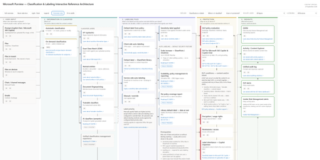
In April, I published a set of referential architecture diagrams for Microsoft Purview — Microsoft Purview Referential Architecture Diagrams. They have been useful in workshops and training sessions for a simple reason: one picture is worth a thousand words - attempting to explain the complex in a single image. Today I'm publishing an update focused on classification and labeling — and on the wave of public previews that make auto-labeling something you can scale across the entire estate with ease. ➡️ Download the interactive architecture on GitHub here. It's a self-contained HTML file - and it's a lot more than this picture! Why now: auto-labeling scales to the whole estate The most consequential change is surprisingly small. An auto-labeling policy can now be kept on while you edit it, without re-triggering simulation. Anyone who has run auto-labeling at scale knows why that matters. Until now, tuning a policy meant turning enforcement off, re-simulating, waiting, and turning it back on — delays every time you refined a rule. That friction made it challenging for organizations from broadening scope as fast as they wanted to. Removing it changes the operating model: you can simulate once with your conditions and expand scope (sites) when you're ready, without hitting the simulation limit. It arrives alongside a set of previews that lift every ceiling that used to cap the motion: Capacity is up 5x. Auto-labeling for SharePoint and OneDrive moves from 100,000 to up to 500,000 files per tenant per day (Roadmap ID 567890). Simulation goes from 4M to 20M items, so you can model against a real estate rather than a sample. Policy scope gets much bigger. Select up to 1,000 individual SharePoint sites per policy, adaptive scopes support up to 50,000 sites, and you can filter sites by the SiteTemplate property when configuring a policy (Roadmap ID 570445, MC1469958). Reporting finally tells you what happened. Audit and reporting now summarize the sensitive information types detected when labels are applied, and a new 30-day chart shows files processed per day so you can watch policy throughput. A per-policy coverage report correlates files processed during enforcement to the latest simulation run — including the files that enforcement processed but simulation never saw (Roadmap ID 568935). SharePoint library default labels now reach data at rest, applying the library's default label to existing files instead of only new or edited ones (Roadmap ID 559105, MC1477181). Read together, these are one story: classify and label the whole estate — unblocking your Microsoft 365 Copilot deployment by securing the data that matters to you most. The scalability improvements are on by default, and existing policies continue to function unmodified with no end-user impact. What the architecture shows The diagram follows content through five stages, each framed as the question it answers: User input — where information originates: files, email, Teams messages, files on devices, files in transit, and prompts. Information is classified — what is it? SITs, Exact Data Match, named entities, document fingerprinting, trainable classifiers, and AI classifiers, with automatic (in-transit) and on-demand (at-rest) classification as the two entry paths. Labeling files — what is the default security posture, and what did the user intend? Five labeling methods — default label from policy, client-side, library default, service-side auto-labeling, and manual — all converging on one node: the label is applied. Protection — what do we do about it? DLP (including DLP for Copilot), encryption and usage rights, permissions, label inheritance on Copilot responses, Adaptive Protection, and retention. Insights — what did we learn? DSPM, Activity and Content Explorer, the unified audit log, DLP alerts, and Insider Risk alerts. How to use it - it's interactive! It's a single self-contained HTML file — no dependencies or API call — it works offline. Click any node to light up its full upstream and downstream path; everything unrelated dims. The detail panel then shows what it feeds from, what it feeds into, what it sees, what it can do, and — the section I'd argue matters most — what it can't do. Explain runs three guided walkthroughs: Classification vs labels, When is it classified?, and How is it protected? These are my go-to openers for a workshop. Isolate layer cuts the diagram by control plane — sensitivity label, SITs, classifiers, DLP, encryption, permissions, retention, audit. Licensing lens filters to Included in E3, E5 only — the delta over E3, or Pay-as-you-go. Use it to answer entitlement questions honestly: where Microsoft publishes no SKU, the node says so instead of guessing. Always confirm entitlements on a quote, not from a diagram. Overview only strips to titles for a clean read; Fit to width scales the whole thing to the window; light/dark follows your OS or the toggle; it prints cleanly to PDF. Keyboard: Tab between nodes, Enter to select, Esc to reset. Auto-labeling at scale If you're standing up auto-labeling at scale, confirm the prerequisites node first — sensitivity labels enabled for Office files in SharePoint and OneDrive, PDF support enabled separately via EnableSensitivityLabelForPDF, auditing on (simulation requires it), labels published to at least one user, and label scope covering Files and/or Emails. Simulate on your priority sites, review, enforce, then expand scope to more sites or all sites and keep going. Combine that with capabilities already GA — labeling files contextually by site + file types, and overriding manually applied labels — and you can finally clear the backlog of unlabeled files. note: more to come soon for a full deployment guide. Feedback welcome — if a node is wrong, missing a limitation, or missing a link, tell me in the comments and I'll fix it in the next revision.1.9KViews5likes1Comment
Feature Request: Extend Security Copilot inclusion (M365 E5) to M365 A5 Education tenants
Background At Ignite 2025, Microsoft announced that Security Copilot is included for all Microsoft 365 E5 customers, with a phased rollout starting November 18, 2025. This is a significant step forward for security operations. The gap Microsoft 365 A5 for Education is the academic equivalent of E5 — it includes the same core security stack: Microsoft Defender, Entra, Intune, and Purview. However, the Security Copilot inclusion explicitly covers only commercial E5 customers. There is no public roadmap or timeline for extending this benefit to A5 education tenants. Why this matters Education institutions face the same cybersecurity threats as commercial organizations — often with fewer dedicated security resources. The A5 license was positioned as the premium security offering for education. Excluding it from Security Copilot inclusion creates an inequity between commercial and education customers holding functionally equivalent license tiers. Request We would like Microsoft to: Confirm whether Security Copilot inclusion will be extended to M365 A5 Education tenants If yes, provide an indicative timeline If no, clarify the rationale and what alternative paths exist for education customers Are other EDU admins in the same situation? Would appreciate any upvotes or comments to help raise visibility with the product team.1.4KViews16likes4CommentsPost-Quantum Cryptography Comes to Windows Insiders and Linux
Introduction As the digital landscape continues to evolve, the emergence of quantum computing presents both significant opportunities and challenges. In previous blog posts, we discussed how quantum computing could disrupt contemporary cryptographic algorithms, Microsoft’s contributions to quantum safety efforts across the industry, and the addition of PQC algorithms to SymCrypt, our core cryptographic library. We are pleased to announce the next significant milestone in our PQC journey: We’re making PQC capabilities available for Windows Insiders, Canary Channel Build 27852 and higher, and Linux, SymCrypt-OpenSSL version 1.9.0. This advancement will enable customers to commence their exploration and experimentation of PQC within their operational environments. By obtaining early access to PQC capabilities, organizations can proactively assess the compatibility, performance, and integration of these novel algorithms alongside their existing security infrastructure. This practical approach helps security teams identify potential challenges, optimize implementation strategies, and enable an easier transition as industry standards evolve. Furthermore, early adoption will offer valuable insights into the ways in which PQC can help mitigate emerging threats, thereby positioning organizations to more effectively protect sensitive data against future quantum threats. What’s new in Windows Windows, being one of the most widely used operating systems globally, plays a crucial role in the digital ecosystem. Taking the addition of PQC algorithms to SymCrypt a step further, we’re excited to bring ML-KEM and ML-DSA to our Windows Insiders via updates to the Cryptography API: Next Generation (CNG) libraries and Certificate and Cryptographic messaging functions. Developers can begin experimenting with ML-KEM in scenarios where public key encapsulation or key exchange is desired, to help prepare for “harvest now, decrypt later” threat. The table below describes the parameter sets included in this update. We encourage customers to use a hybrid approach, using ML-KEM alongside existing algorithms (like ECDH or RSA) during transition for defense in depth, with preference for NIST security level 3 and above where possible, based on the need and threat model. Public (encapsulation) key size Ciphertext size Shared secret size NIST security level ML-KEM 512 800 bytes 768 bytes 32 bytes Level 1 ML-KEM 768 1184 bytes 1088 bytes 32 bytes Level 3 ML-KEM 1024 1568 bytes 1568 bytes 32 bytes Level 5 The addition of ML-DSA in Cryptography API: Next Generation (CNG) enables developers to begin experimenting with PQC algorithms for scenarios that require verification of identity, integrity or authenticity using digital signatures. We encourage customers to use a composite approach, using ML-DSA alongside existing algorithms (like ECDSA or RSA) during transition. Our preliminary analysis indicates that size and performance will have some impact. We encourage you to begin this analysis early to understand the effects on your environment and applications. Public key size Private key size Signature size NIST security level ML-DSA-44 1312bytes 2560 bytes 2420bytes Level 2 ML-DSA-65 1952 bytes 4032 bytes 3309 bytes Level 3 ML-DSA-87 2592 bytes 4896 bytes 4627 bytes Level 5 With PQC updates in wincrypt, the Windows certificate API surface, customers can experiment with installing, importing and exporting ML-DSA certificates to and from the certificate store. Customers can also experiment with validating PQ certificate chains and trust status. Visit our crypto developer's page to learn more about how you can get started. While the changes here correspond to the NIST standardized algorithms, we will continue to iterate and make updates as the standards evolve and what is required for quantum-resistant cryptography changes. What’s new in Linux As we progress in helping make PQC available to our Windows customers through CNG and SymCrypt, it is important to acknowledge that many of our Linux users are anticipating PQC updates in the SymCrypt provider for OpenSSL 3. This provider is a natural way for Linux programmers to use OpenSSL’s API surface powered by SymCrypt cryptographic operations. With version 1.9.0 of SymCrypt-OpenSSL, we are enabling customers to experiment with TLS hybrid key exchange as per the latest IETF internet draft, providing an early opportunity to help prepare for “harvest now, decrypt later” threats. Furthermore, this functionality empowers customers to conduct in-depth analysis of how integrating PQC algorithms in a hybrid mode impacts handshake message sizes, changes TLS handshake latency, and has effects on overall connection efficiency. Such investigations are crucial for understanding the operational trade-offs of adopting PQC, enabling informed decisions as organizations prepare for a future where quantum-resistant security becomes fundamental. It is important to note that these changes are based on draft specifications, and as the standards evolve, we will update the SymCrypt-OpenSSL implementation to enable interoperability and compliance. What’s coming next The integration of PQC into Windows Insiders and Linux marks an important first step in enabling our customers to explore PQC within their environments. This is just the beginning—more capabilities and enhancements are on the way. Alongside the addition of SLH-DSA to SymCrypt, CNG and SymCrypt-OpenSSL, we plan to incorporate further algorithms to enable continued compliance with global regulations, robust security, and broad compatibility as PQC standards mature. The PKI and certificate standards are gaining momentum within the LAMPS working group in IETF. We are collaborating with industry partners on X.509 standardizations concerning the general use of ML-DSA, composite ML-DSA, SLH-DSA, ML-KEM, composite ML-KEM and LMS/XMSS. These efforts will be relevant to various signature schemes and PKI use cases, including those used in firmware and software signing. The use of PQC algorithms to secure TLS communications is rapidly evolving. While we’ve introduced hybrid key exchange through SymCrypt-OpenSSL for Linux, we’re actively working to get this capability to our Windows customers via the Windows TLS stack (Schannel). We’re also collaborating with the IETF to develop and standardize quantum-safe authentication mechanisms including Composite ML-DSA, pure ML-DSA and SLH-DSA for TLS and other IETF protocols. As these standards are finalized, we will make them available through both the Windows TLS stack (Schannel), SymCrypt provider for OpenSSL and SymCrypt Rust Wrapper on Linux. It is important to note that TLS 1.3 will be a prerequisite for PQC, and we strongly advise customers to start transitioning from older TLS protocols if they have not already. For more information, see Taking Transport Layer Security (TLS) to the next level with TLS 1.3. Another area we’re actively working on is helping support PQC algorithms within Microsoft Active Directory Certificate Services (ADCS). This will enable customers configuring a Certification Authority (CA) to use a CA certificate based on PQC algorithms such as ML-DSA. Clients will be able to enroll for PQC end-entity certificates, and the Certificate Revocation Lists (CRLs) issued by the CA will be signed using PQC algorithms. Support will be extended across all relevant ADCS role services, including the Certificate Enrollment Policy (CEP) and Certificate Enrollment Services (CES), the Network Device Enrollment Service (NDES), and the Online Certificate Status Protocol (OCSP) responder. Microsoft Intune’s certificate delivery mechanism – the Certificate Connector – is being enhanced to help support PQC certificates as well, enabling mobile devices and endpoints can enroll and obtain quantum-safe credentials. Going forward, this connector will be updated to handle certificate requests and deliveries that use PQC keys and signatures, unblocking SCEP & PKCS #12 scenarios for on-premises CAs leveraging ADCS. These new capabilities will be introduced for experimentation through Windows Insiders and development channels, helping provide early access to organizations and individuals eager to test PQC features within real-world environments. By leveraging these preview channels, Microsoft can gather critical feedback on interoperability, security, and usability, allowing for iterative improvements before wide-scale release. As global standards for PQC continue to evolve, Microsoft remains committed to a flexible and adaptive deployment strategy. This approach allows that once standards are finalized, the more robust and interoperable solutions can be more easily brought to supported platform versions across both Windows and Linux ecosystems. Furthermore, collaboration with industry partners and standards bodies will help guarantee that emerging features align with broader ecosystem desires and global regulatory requirements, accelerating the journey toward quantum-safe security for organizations of all sizes. Future Perspectives and Challenges PQC algorithms are relatively new, and it is prudent not to consider the initial generation of PQC algorithms as the definitive solution but rather view this as an evolving field. This underscores the importance of "Crypto Agility" which involves designing solutions to be more resilient to the use of different algorithms and/or upgradable to use future algorithms as the PQ standards evolve. Recognizing this, Microsoft is a strong advocate of building solutions which are crypto agile, as well as deploying PQC solutions which make use of a hybrid PQ mode of operation. These hybrid modes, including TLS hybrid key exchange or composite certificates, use both a PQ algorithm and a traditional algorithm such as RSA or ECDHE. In time, we anticipate a shift towards pure PQ deployments, as PQ algorithms and standards mature. While the integration of PQC into Windows Insiders and Linux is an important milestone, several challenges remain. The performance of PQC algorithms, compatibility with existing systems, and the desire for widespread adoption are fundamental factors that will determine the success of this transition. Performance Considerations PQC algorithms often require more computational resources than their classical counterparts. Enabling these algorithms can be more efficiently implemented without significantly impacting system performance is a key challenge. Continuous optimization and hardware acceleration techniques are important to achieve a balance between security and performance. Many PQ algorithms, such as ML-KEM and ML-DSA, use Keccak (the basis for SHA-3, SHAKE, and related functions) for pseudo-random value generation and input integrity checks. As PQC adoption grows, improving Keccak performance—especially with hardware acceleration—will be key to efficient cryptography, reducing resource demands and helping boost security for post-quantum operations. When used in the TLS protocol, the larger sizes of PQC key encapsulation mechanisms and digital signatures, especially when used in a hybrid mode, may add to the round-trip time to establish and communicate over a secure network channel. Some IETF drafts are in progress that aim to help improve this, including TLS key share prediction for faster cipher suite negotiation and TLS certificate compression to reduce the size of certificates, but note that signatures cannot be compressed. We recommend that you assess the impact of these modifications on your environment and applications. Compatibility and Adoption The transition to PQC will require updating and replacing existing cryptographic infrastructure across various platforms and applications. Enabling compatibility with legacy systems and achieving widespread adoption will necessitate coordinated efforts among software developers, hardware manufacturers, and service providers. Education and awareness campaigns will also play an important role in encouraging organizations to embrace post-quantum cryptographic solutions along with compliance timelines set by governments globally. Conclusion The integration of PQC capabilities into Windows Insiders and Linux marks a significant step forward in preparing for the quantum era. Quantum computing has significant potential to help solve some of humanity's greatest challenges, and by proactively addressing the security concerns with current cryptographic standards, Microsoft is helping pave the way for a digital future that both realizes the benefits of quantum and mitigates the security risks. As quantum computing continues to advance, the adoption of PQC will be crucial in safeguarding our data, communications, and digital infrastructure. Through collaboration and innovation, we can help build a resilient and secure digital ecosystem that stands the test of time. Securing the Present, Innovating for the Future Security is a shared responsibility. Through collaboration across hardware and software ecosystems, we can build more resilient systems secure by design and by default, from Windows to the cloud, enabling trust at every layer of the digital experience. The updated Windows Security book and Windows Server Security book are available to help you understand how to stay secure with Windows. Learn more about Windows 11, Windows Server and Copilot+ PCs.. To learn more about Microsoft Security Solutions, visit our website. Bookmark the Security blog to keep up with our expert coverage on security matters. Also, follow us on LinkedIn (Microsoft Security) and X (@MSFTSecurity) for the latest news and updates on cybersecurity.Security baseline for Microsoft Edge version 151
We are pleased to announce the enterprise-ready release of the security baseline for Microsoft Edge version 151! We have reviewed the settings in Microsoft Edge version 151 and updated our guidance with six new recommendations. We have also identified one additional setting that organizations should consider evaluating in their environments. A new Microsoft Edge security baseline package was just released to the Download Center. You can download the new package from the Security Compliance Toolkit. Enable Process Isolation (added) We are enforcing ‘Enable Process Isolation’ to help protect Microsoft Edge from unauthorized access, modification, and tampering by other applications running on the device. This setting strengthens browser process integrity and helps safeguard sensitive data used by Microsoft Edge. Organizations that encounter compatibility issues with software that depends on browser process injection should treat such configurations as exceptions requiring explicit risk acceptance and compatibility validation. Enable renderer in app container (added) We are enforcing the default and enabling ‘Enable renderer in app container’ to strengthen Microsoft Edge’s browser isolation protections by ensuring renderer processes run within the additional restrictions provided by AppContainer. This helps reduce the impact of browser-based attacks and limits the ability of exploited renderer processes to interact with system resources. Organizations that require this setting to be disabled due to incompatible software should treat such configurations as exceptions that require explicit risk acceptance. Enable the network service sandbox (added) We are enforcing the default and enabling ‘Enable the network service sandbox’ to ensure Microsoft Edge network-facing processes operate within sandbox isolation boundaries that help reduce the impact of exploitation and limit access to system resources. Because disabling the network service sandbox weakens a core browser security protection, organizations should treat any requirement to disable this setting as an exception scenario requiring explicit risk acceptance and compatibility validation. Configure browser process code integrity guard (added) We are enabling ‘Configure browser process code integrity guard setting’ with a value of ‘Enable code integrity guard enforcement in the browser process’. The setting strengthens protections against unauthorized code injection into Microsoft Edge browser processes. Some enterprise applications, extensions, accessibility tools, or security products may still rely on legacy injection techniques and require compatibility validation. We encourage organizations to fully test this setting in their environments and work with vendors to identify or remediate incompatible software. Enable Application Bound Encryption (added) We are enabling ‘Enable Application Bound Encryption’ to strengthen protections for browser-stored credentials, authentication tokens, and other sensitive data by binding encryption more closely to the browser process. This helps reduce the risk of unauthorized access to protected browser data by malware or other untrusted software. Because disabling this setting weakens an important protection boundary, organizations should treat any requirement to disable the feature as an exception requiring explicit risk review. Enhance the security state in Microsoft Edge (added) We are enabling ‘Enhance the security state in Microsoft Edge’ and configuring the setting to Balanced to provide additional protection against modern web-based attacks while maintaining compatibility for most enterprise users. In Balanced mode, Microsoft Edge applies additional mitigations such as disabling just-in-time (JIT) JavaScript compilation and enabling added operating system protections on processes used to load sites that users do not frequently visit, helping reduce the risk of memory-related vulnerabilities. Because these protections can introduce compatibility issues for some applications or workflows, organizations should validate critical business sites and applications during their normal testing process prior to broad deployment and configure exceptions as needed. Additional details can be found here. Configure Automatic HTTPS (worth considering) We previously released a blog discussing a new feature called Automatic HTTPS. This setting can automatically switch your connections to websites from HTTP to HTTPS on sites that are highly likely to support the more secure protocol. This option helps ensure that users' network traffic is more secure and less susceptible to SSL stripping attacks. The best part, the end user doesn’t get prompted, it just works! This new feature has two configuration options: Navigations delivered over HTTP are switched to HTTPS’ (UpgradeCapableDomains) and ‘All navigation delivered over HTTP are switched to HTTPS’ (AlwaysUpgrade). There are trade-offs for each configuration: the UpgradeCapableDomains option only upgrades to HTTPS if Microsoft believes the site is likely to work over HTTPS, and this setting is unavailable if you’ve disabled the ComponentUpdatesEnabled policy. The more secure AlwaysUpgrade option unconditionally updates all HTTP requests to HTTPS, which will result in a user-visible error page if the target site does not support HTTPS. We encourage organizations to consider implementing and testing Automatic HTTPS within their environment. Collectively, these changes continue our focus on strengthening browser isolation, sandboxing, process integrity, and protection of sensitive browser data while balancing enterprise compatibility requirements. Microsoft Edge version 151 introduced 4 new computer and user settings. We have included a spreadsheet listing the new settings in the release to make it easier for you to find them. As a friendly reminder, all available settings for Microsoft Edge are documented here, and all available settings for Microsoft Edge Update are documented here. Please continue to give us feedback through the Security Baseline Community or in comments on this post.1.8KViews0likes6CommentsMigrate Sentinel to Defender - Why It Is a Security Architecture Decision, Not Just a Portal Change
Microsoft will retire the Sentinel experience in Azure on March 31, 2027. Most of the conversation around this transition focuses on cost optimization and portal consolidation. That framing undersells what is actually happening. The unified Defender portal is not a new interface for the same capabilities. It is the platform foundation for a fundamentally different SOC operating model — one built on a 2-tier data architecture, graph-based investigation, and AI agents that can hunt, enrich, and respond at machine speed. Partners who understand this will help customers build security programs that match how attackers actually operate. This document covers four things: What the unified experience delivers — the security capabilities that do not exist in standalone Sentinel and why they matter against today’s threats. What the transition really involves - is not data migration, but it is a data architecture project that changes how telemetry flows, where it lives, and who queries it. Where the partner opportunity lives — a structured progression from professional services (transactional, transition execution, and advisory) to ongoing managed security services. Why does the unified experience win competitively — factual capability advantages that give partners a defensible position against third-party SIEM alternatives. The Bigger Picture: Preparing for the Agentic SOC Before getting into transition mechanics, partners need to understand where the industry is headed — because the platform decisions made during this transition will determine whether a customer’s SOC is ready for what comes next. The security industry is moving from human-driven, alert-centric workflows to an operating model built on three pillars: Intellectual Property — the detection logic, hunting hypotheses, response playbooks, and domain expertise that differentiate one security team from another. Human Orchestration — the judgment, context, and decision-making that humans bring to complex incidents. Humans set strategy, validate findings, and make containment decisions. They do not manually triage every alert. AI Agents - built agents that execute repeatable work: enriching incidents, hunting across months of telemetry, validating security posture, drafting response actions, and flagging anomalies for human review. The SOC of 2027 will not be scaled by hiring more analysts. It will be scaled by deploying agents that encode institutional knowledge into automated workflows — orchestrated by humans who focus on the decisions that require judgment. This transformation requires a platform that provides three things: Deep telemetry — agents need months of queryable data to analyze behavioral patterns, build baselines, and detect slow-moving threats. The Sentinel data lake provides this at a cost point that makes long-retention feasible. Relationship context — agents need to understand how entities connect. Which accounts share credentials? What is the blast radius of a compromised service principle? What is the attack path from a phished user to domain admin? Sentinel Graph provides this. Extensibility — partners and customers need to build and deploy their own agents without waiting for Microsoft to ship them. The MCP framework and Copilot agent architecture provide this. None of these exist in Azure experience for Sentinel. All three ship with the Defender experience. The urgency goes beyond the March 2027 deadline. Organizations are deploying AI agents, copilots, and autonomous workflows across their businesses — and every one of those creates a new attack surface. Prompt injection, data poisoning, agent hijacking, cross-plugin exploitation — these are not theoretical risks. They are in the wild today. Defending against AI-powered attacks requires a security platform that is itself AI Agent-ready. The new experience in Defender unlocks this experience. What Unified SIEM and XDR Actually Delivers The original framing — “single pane of glass for SIEM and XDR” — is accurate but insufficient. Here is what the unified platform delivers that standalone Sentinel does not. Cross-Domain Incident Correlation The Defender correlation engine does not just group alerts by time proximity. It builds multi-stage incident graphs that link identity compromise to lateral movement to data exfiltration across SIEM and XDR telemetry — automatically. Consider a token theft chain: an infostealer harvests browser session cookies (endpoint telemetry), the attacker replays the token from a foreign IP (Entra ID sign-in logs), creates a mailbox forwarding rule (Exchange audit logs), and begins exfiltrating data (DLP alerts). In standalone Sentinel, these are four separate alerts in four different tables. In the unified platform, they are one correlated incident with a visual attack timeline. 2-Tier Data Architecture The Sentinel data lake introduces a second storage tier that changes the economics and capabilities of security telemetry: Analytics Tier Data Lake Purpose Real-time detection rules, SOAR, alerting Hunting, forensics, behavioral analysis, AI agent queries Latency Sub-5-minute query and alerting Minutes to hours acceptable Cost ~$4.30/GB PAYG ingestion (~$2.96 at 100 GB/day commitment) ~$0.05/GB ingestion + $0.10/GB data processing (at least 20x cheaper) Retention 90 days default (expensive to extend) Up to 12 years at low cost Best for High-signal, low-volume sources High-volume, investigation-critical sources The architecture decision is not “which tier is cheaper.” It is “which tier gives me the right detection capability for each data source.” Analytics tier candidates: Entra ID sign-in logs, Azure activity, audit logs, EDR alerts, PAM events, Defender for Identity alerts, email threat detections. These need sub-5-minute alerting. Data lake candidates: Raw firewall session logs, full DNS query streams, proxy request logs, Sysmon process events, NSG flow logs. These drive hunting and forensic analysis over weeks or months. Dual-ingest sources: Some sources need both tiers. Entra ID sign-in logs are the canonical example — analytics tier for real-time password spray detection, Data Lake for graph-based blast radius analysis across months of authentication history. Implementation is straightforward: a single Data Collection Rule (DCR) transformation handles the split. One collection point, two routing destinations. The right framing: “Right data in the right tier = better detections AND lower cost.” Cost savings are a side effect of good security architecture, not the goal. Sentinel Graph Sentinel graph enables SOC teams and AI agents to answer questions that flat log queries cannot: What is the blast radius of this compromised account? Which service principals share credentials with the breached identity? What is the attack path from this phished user to domain admin? Which entities are connected to this suspicious IP across all telemetry sources? Graph-based investigation turns isolated alerts into context-rich intelligence. It is the difference between knowing “this account was compromised” and understanding “this account has access to 47 service principals, 3 of which have written access to production Key Vault.” Security Copilot Integration Security Copilot embedded in the defender portal helps analysts summarize incidents, generate hunting queries, explain attacker behavior, and draft response actions. For complex multi-stage incidents, it reduces the time from “I see an alert” to “I understand the full scope” from hours to minutes. With free SCUs available with Microsoft 365 E5, teams can apply AI to the highest-effort investigation work without adding incremental cost. MCP and the Agent Framework The Model Context Protocol (MCP) and Copilot agent architecture let partners and customers build purpose-built security agents. A concrete example: an MCP-enabled agent can automatically enrich a phishing incident by querying email metadata, checking the sender against threat intelligence, pulling the user’s recent sign-in patterns, correlating with Sentinel Graph for lateral risk, and drafting a containment recommendation — in under 60 seconds. This is where partner intellectual property becomes competitive advantage. The agent framework is the mechanism for encoding proprietary detection logic, response playbooks, and domain expertise into automated workflows that run at machine speed. Security Store Security Store allows partners to evolve from one‑time transition projects into repeatable, scalable offerings—supporting professional services, managed services, and agent‑based IP that align with the customer’s unified SecOps operating model As part of the transition, the Microsoft Security Store becomes the extension layer for the Defender —allowing partners to deliver differentiated agents, SaaS, and security services natively within Defender and Sentinel, instead of building and integrating in isolation The 4 Investigation Surfaces: A Customer Maturity Ladder The Sentinel Data Lake exposes four distinct investigation surfaces, each representing a step toward the Agentic SOC — and a partner service opportunity: Surface Capability Maturity Level Partner Opportunity KQL Query Ad-hoc hunting, forensic investigation Basic — “we can query” Hunting query libraries; KQL training Graph Analytics Blast radius, attack paths, entity relationships Intermediate — “we understand relationships” Graph investigation training; attack path workshops Notebooks (PySpark) Statistical analysis, behavioral baselines, ML models Advanced — “we predict behaviors” Custom notebook development; anomaly scoring Agent/MCP Access Autonomous hunting, triage, response at machine speed Agentic SOC — “we automate” Custom agent development; MCP integration The customer who starts with “help us hunt better” ends up at “build us agents that hunt autonomously.” That is the progression from professional services to managed services. What the Transition Actually Involves It is not a data migration — customers’ underlying log data and analytics remain in their existing Log Analytics workspaces. That is important for partners to communicate clearly. But partners should not set the expectation that nothing changes except the URL. Microsoft’s official transition guide documents significant operational changes — including automation rules and playbooks, analytics rule, RBAC restructuring to the new unified model (URBAC), API schema changes that break ServiceNow and Jira integrations, analytics rule transitions where the Fusion engine is replaced by the Defender XDR correlation engine, and data policy shifts for regulated industries. Most customers cannot navigate this complexity without professional help. Important: Transitioning to the Defender portal has no extra cost - estimate the billing with the new Sentinel Cost Estimator Optimizing the unified platform means making deliberate changes: Adding dual-ingest for critical sources that need both real-time detection and long-horizon hunting. Moving high-volume telemetry to the Data Lake — enabling hunting at scale that was previously cost-prohibitive. Retiring redundant data copies where Defender XDR already provides the investigation capability. Updating RBAC, automation, and integrations for the unified portal’s consolidated schema and permission structure. Training analysts on new investigation workflows, Sentinel Graph navigation, and Copilot-assisted triage. Threat Coverage: The Detection Gap Most Organizations Do Not Know They Have This transition is an opportunity to quantify detection maturity — and most organizations will not like what they find. Based on real-world breach analysis — infostealers, business email compromise, human-operated ransomware, cloud identity abuse, vulnerability exploitation, nation-state espionage, and other prevalent threat categories — organizations running standalone Sentinel with default configurations typically have significant detection gaps. Those gaps cluster in three areas: Cross-domain correlation gaps — attacks that span identity, endpoint, email, and cloud workloads. These require the Defender correlation engine because no single log source tells the complete story. Long-retention hunting gaps — threats like command-and-control beaconing and slow data exfiltration that unfold over weeks or months. Analytics-tier retention at 90 days is too expensive to extend and too short for historical pattern analysis. Graph-based analysis gaps — lateral movement, blast radius assessment, and attack path analysis that require understanding entity relationships rather than flat log queries. The unified platform with proper log source coverage across Microsoft-native sources can materially close these gaps — but only if the transition includes a detection coverage assessment, not just a portal cutover. Partners should use MITRE ATT&CK as the common framework for measuring detection maturity. Map existing detections to ATT&CK tactics and techniques before and after transition — a measurable, defensible improvement that justifies advisory fees and ongoing managed services. Partner Opportunity: Professional Services to Managed Services This transition creates a structured progression for all partner types — from professional services that build trust and surface findings, to managed security services that deliver ongoing value. The key insight most partners miss: do not jump from “transition assessment” to “managed services pitch.” Customers are not ready for that conversation until they have experienced the value of professional services. The bridge engagement — whether transactional, transition execution, or advisory — builds trust, demonstrates the expertise, and surfaces the findings that make the managed services conversation a logical next step. Professional Services (transactional + transition execution + advisory) → Managed Security Services (MSSP) The USX transition is the ideal professional services entry point because it combines a mandatory deadline (March 2027) with genuine technical complexity (analytics rule, automation behavioral changes, RBAC restructuring, API schema shifts) that most customers cannot navigate alone. Every engagement produces findings — detection gaps, automation fragility, staffing shortfalls — that are the most credible possible evidence for managed services. Professional Services Transactional Partners Offer Customer Value Key Deliverables Transition Readiness Assessment Risk-mitigated transition with clear scope Sentinel deployment inventory; Defender portal compatibility check; transition roadmap with timeline; MITRE ATT&CK detection coverage baseline Transition Execution and Enablement Accelerated time-to-value, minimal disruption Workspace onboarding; RBAC and automation updates; Dual-portal testing and validation; SOC team training on unified workflows Security Posture and Detection Optimization Better detections and lower cost Data ingestion and tiering strategy; Dual-ingest implementation for critical sources; Detection coverage gap analysis; Automation and Copilot/MCP recommendations Advisory Partners Offer Customer Value Key Deliverables Executive and Strategy Advisory Leadership alignment on why this transition matters Unified SecOps vision and business case; Zero Trust and SOC modernization alignment; Stakeholder alignment across security, IT, and leadership Architecture and Design Advisory Future-ready architecture optimized for the Agentic SOC Target-state 2-tier data architecture; Dual-ingest routing decisions mapped to MITRE tactics; RBAC, retention, and access model design Detection Coverage and Gap Analysis Measurable detection maturity improvement Current-state MITRE ATT&CK coverage mapping; Gap analysis against 24 threat patterns; Detection improvement roadmap with priority recommendations SOC Operating Model Advisory Smooth analyst adoption with clear ownership Redesigned SOC workflows for unified portal; Incident triage and investigation playbooks; RACI for detection engineering, hunting, and platform ops Agentic SOC Readiness Preparation for AI-driven security operations MCP and agent architecture assessment; Custom agent development roadmap; IP + Human Orchestration + Agent operating model design Cost, Licensing and Value Advisory Transparent cost impact with strong business case Current vs. future cost analysis; Data tiering optimization recommendations; TCO and ROI modeling for leadership The conversion to managed services is evidence-based. Every professional services engagement produces findings — detection gaps, automation fragility, staffing shortfalls. Those findings are the most credible possible case for ongoing managed services. Managed Security Services The unified platform changes the managed security conversation. Partners are no longer selling “we watch your alerts 24/7.” They are selling an operating model where proprietary AI agents handle the repeatable work — enrichment, hunting, posture validation, response drafting — and human experts focus on the decisions that require judgment. This is where the competitive moat forms. The formula: IP + Human Orchestration + AI Agents = differentiated managed security. The unified platform enables this through: Multi-tenancy — the built-in multitenant portal eliminates the need for third-party management layers. Sentinel Data Lake — agents can query months of customer telemetry for behavioral analysis without cost constraints. Sentinel Graph — agents can traverse entity relationships to assess blast radius and map attack paths. MCP extensibility — partners can build agents that integrate with proprietary tools and customer-specific systems. Partners who build proprietary agents encoding their detection logic into the MCP framework will differentiate from partners who rely on out-of-box capabilities. The Securing AI Opportunity Organizations are deploying AI agents, copilots, and autonomous workflows across their businesses at an accelerating pace. Every AI deployment creates a new attack surface — prompt injection, data poisoning, agent hijacking, cross-plugin exploitation, unauthorized data access through agentic workflows. These are not theoretical risks. They are in the wild today. Partners who can help customers secure their AI deployments while also using AI to strengthen their SOC will command premium positioning. This requires a security platform that is itself AI Agent-ready — one that can deploy defensive agents at the same pace organizations deploy business AI. The unified Defender portal is that platform. Partners who position USX as “preparing your SOC for AI-driven security operations” will differentiate from partners who position it as “moving to a new portal.” Cost and Operational Benefits Better security architecture also costs less. This is not a contradiction — it is the natural result of putting the right data in the right tier. Benefit How It Works Eliminate low-value ingestion Identify and remove log sources that are never used for detections, investigations, or hunting. Immediately lowers analytics-tier costs without impacting security outcomes. Right-size analytics rules Disable unused rules, consolidate overlapping detections, and remove automation that does not reduce SOC effort. Pay only for processing that delivers measurable security value. Avoid SIEM/XDR duplication Many threats can be investigated directly in Defender XDR without duplicating telemetry into Sentinel. Stop re-ingesting data that Defender already provides. Tier data by detection need Store high-volume, hunt-oriented telemetry in the Data Lake at at least 20x lower cost. Promote only high-signal sources to the analytics tier. Full data fidelity preserved in both tiers. Reduce operational overhead Unified SIEM+XDR workflows in a single portal reduce tool switching, accelerate investigations, simplify analyst onboarding, and enable SOC teams to scale without proportional headcount increases. Improve detection quality The Defender correlation engine produces higher-fidelity incidents with fewer false positives. SOC teams spend less time triaging noise and more time on real threats. Competitive Positioning Partners need defensible talking points when customers evaluate third-party SIEM alternatives. The following advantages are factual, sourced from Microsoft’s transition documentation and platform capabilities — not marketing claims. No extra cost for transitioning — even for non-E5 customers. Third-party SIEM migrations involve licensing, data migration, detection rewrite, and integration rebuild costs. Native cross-domain correlation across Sentinel + Defender products into multi-stage incident graphs. Third-party SIEMs receive Microsoft logs as flat events — they lack the internal signal context, entity resolution, and product-specific intelligence that powers cross-domain correlation. Custom detections across SIEM + XDR — query both Sentinel and Defender XDR tables without ingesting Defender data into Sentinel. Eliminates redundant ingestion cost. Alert tuning extends to Sentinel — previously Defender-only capability, now applicable to Sentinel analytics rules. Net-new noise reduction. Unified entity pages — consolidated user, device, and IP address pages with data from both Sentinel and Defender XDR, plus global search across SIEM and XDR. Third-party SIEMs provide entity views from ingested data only. Built-in multi-tenancy for MSSPs — multitenant portal manages incidents, alerts, and hunting across tenants without third-party management layers. Try out the new GDAP capabilities in Defender portal. Industry validation: Microsoft’s SIEM+XDR platform has been recognized as a Leader by both Forrester (Security Analytics Platforms, 2025) and Gartner (SIEM Magic Quadrant, 2025). Summary: What Partners Should Take Away Topic Key Message Framing USX is a security architecture transformation, not a portal transition. Lead with detection capability, not cost savings. Platform foundation Sentinel Data Lake + Sentinel Graph + MCP/Agent Framework = the platform for the Agentic SOC. 4 investigation surfaces KQL → Graph → Notebooks → Agent/MCP. A maturity ladder from “we can query” to “we automate at machine speed.” Architecture 2-tier data model (analytics + Data Lake) with dual-ingest for critical sources. Cost savings are a side effect of good architecture. Transition complexity Analytics rules and automation rules. API schema changes. RBAC restructuring. Most customers need professional help. Partner engagement model Professional Services (transactional + transition execution + advisory) → Managed Services (MSSP). Competitive positioning No extra cost. Native correlation. Cross-domain detections. Built-in multi-tenancy. Capabilities third-party SIEMs cannot replicate. Partner differentiation IP + Human Orchestration + AI Agents. Partners who build proprietary agents on MCP have competitive advantage. Timeline March 31, 2027. Start now — phased transition with one telemetry domain first, then scale.3.5KViews5likes5Comments