reliability and resiliency in azure
28 TopicsAzure Incident Retrospective - Please register! Session 2 - Tracking ID: SPCX-S1Z
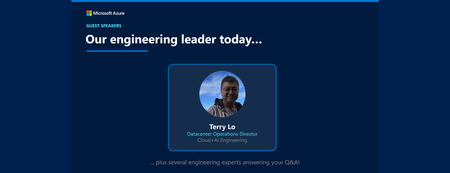
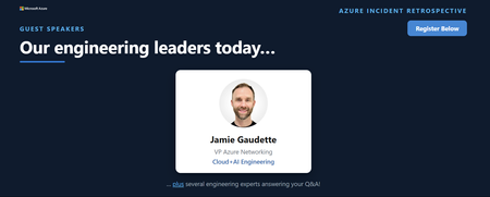
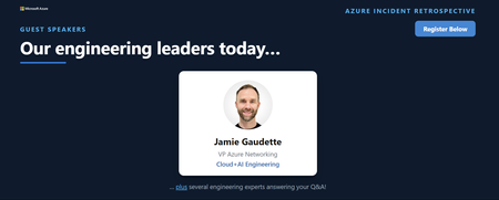
Join our upcoming live webcast for a transparent discussion about this recent Azure service incident led by our engineering teams. Power issue in Southeast Asia Tracking ID: SPCX-S1Z | Impacted: 25-26 August 2026 Same content presented in both sessions: pick the one that works best for your timezone! What to expect 📚 Understand What happened, how we responded, and what we learned 💬 Ask Live Q&A with our engineering experts throughout the session 🛠 Learn The fixes we've put in place and guidance for workload resiliency Choose your session Same content presented at both times: pick the one that works best for your timezone: Session 1 15:30 UTC Thursday, 24 Sept 2026 Register now → Session 2 03:30 UTC Friday, 25 Sept 2026 Register now → 8:30 AM US Pacific (PDT) 11:30 AM US Eastern (EDT) 4:30 PM London (BST) 11:30 PM Beijing (CST) 1:30 AM +1 Sydney (AEDT) 3:30 AM +1 Auckland (NZDT) 8:30 PM -1 US Pacific (PDT) 11:30 PM -1 US Eastern (EDT) 4:30 AM London (BST) 11:30 AM Beijing (CST) 1:30 PM Sydney (AEDT) 3:30 PM Auckland (NZDT) Our engineering leaders Terry Lo Datacenter Operations Manager Southeast Asia Cloud+AI Engineering LinkedIn ↗ ⚠️ Prepare before the livestream Read the Post Incident Review (PIR) ahead of time so you can ask any follow up questions during the live Q&A Helpful resources 🔔 Azure Service Health Alerts Get alerts for relevant incidents by setting up notifications via email, SMS, or webhook 🎥 Past Retrospective Recordings Watch recordings of previous retrospective livestreams 📄 Azure Post Incident Reviews Learn more about PIRs and the retrospective program101Views0likes0CommentsAzure Incident Retrospective - Please register! Session 1 - Tracking ID: SPCX-S1Z
Join our upcoming live webcast for a transparent discussion about this recent Azure service incident led by our engineering teams. Power issue in Southeast Asia Tracking ID: SPCX-S1Z | Impacted: 25-26 August 2026 Same content presented in both sessions: pick the one that works best for your timezone! What to expect 📚 Understand What happened, how we responded, and what we learned 💬 Ask Live Q&A with our engineering experts throughout the session 🛠 Learn The fixes we've put in place and guidance for workload resiliency Choose your session Same content presented at both times: pick the one that works best for your timezone: Session 1 15:30 UTC Thursday, 24 Sept 2026 Register now → Session 2 03:30 UTC Friday, 25 Sept 2026 Register now → 8:30 AM US Pacific (PDT) 11:30 AM US Eastern (EDT) 4:30 PM London (BST) 11:30 PM Beijing (CST) 1:30 AM +1 Sydney (AEDT) 3:30 AM +1 Auckland (NZDT) 8:30 PM -1 US Pacific (PDT) 11:30 PM -1 US Eastern (EDT) 4:30 AM London (BST) 11:30 AM Beijing (CST) 1:30 PM Sydney (AEDT) 3:30 PM Auckland (NZDT) Our engineering leaders Terry Lo Datacenter Operations Manager Southeast Asia Cloud+AI Engineering LinkedIn ↗ ⚠️ Prepare before the livestream Read the Post Incident Review (PIR) ahead of time so you can ask any follow up questions during the live Q&A Helpful resources 🔔 Azure Service Health Alerts Get alerts for relevant incidents by setting up notifications via email, SMS, or webhook 🎥 Past Retrospective Recordings Watch recordings of previous retrospective livestreams 📄 Azure Post Incident Reviews Learn more about PIRs and the retrospective program72Views0likes0CommentsAzure Retirements Livestream - Please register! Session 2 - Tracking ID: 0P59-60Z
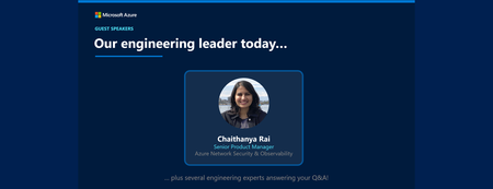
Join our upcoming live webcast for a transparent discussion about this upcoming Azure retirement — led by our engineering teams. Network Security Group (NSG) flow logs in Azure Network Watcher Tracking ID: 0P59-60Z | Retirement Date: 30 September 2027 Same content presented in both sessions — pick the one that works best for your timezone! What to expect 📚 Understand What will happen, the timelines for the change, and how you can manage it 💬 Ask Live Q&A with our engineering experts throughout the session 🛠 Learn How to manage the change smoothly Choose your session Same content presented at both times — pick the one that works best for your timezone: Session 1 16:30 UTC Thursday, 24 Sept 2026 Register now → Session 2 04:30 UTC Friday, 25 Sept 2026 Register now → 9:30 AM US Pacific (PDT) 12:30 PM US Eastern (EDT) 5:30 PM London (BST) 12:30 AM +1 Beijing (CST) 2:30 AM +1 Sydney (AEDT) 4:30 AM +1 Auckland (NZDT) 9:30 PM -1 US Pacific (PDT) 12:30 AM US Eastern (EDT) 5:30 AM London (BST) 12:30 PM Beijing (CST) 2:30 PM Sydney (AEDT) 4:30 PM Auckland (NZDT) Our engineering leaders Chaithanya Rai Senior Product Manager Azure Network Security & Observability LinkedIn ↗ Helpful resources 🔔 Azure Service Health Alerts Get alerts for relevant incidents by setting up notifications via email, SMS, or webhook 🎥 Past Retrospective Recordings Watch recordings of previous retrospective livestreams 📄 Azure Post Incident Reviews Learn more about PIRs and the retrospective program76Views0likes0CommentsAzure Retirements Livestream - Please register! Session 1 - Tracking ID: 0P59-60Z
Join our upcoming live webcast for a transparent discussion about this upcoming Azure retirement — led by our engineering teams. Network Security Group (NSG) flow logs in Azure Network Watcher Tracking ID: 0P59-60Z | Retirement Date: 30 September 2027 Same content presented in both sessions — pick the one that works best for your timezone! What to expect 📚 Understand What will happen, the timelines for the change, and how you can manage it 💬 Ask Live Q&A with our engineering experts throughout the session 🛠 Learn How to manage the change smoothly Choose your session Same content presented at both times — pick the one that works best for your timezone: Session 1 16:30 UTC Thursday, 24 Sept 2026 Register now → Session 2 04:30 UTC Friday, 25 Sept 2026 Register now → 9:30 AM US Pacific (PDT) 12:30 PM US Eastern (EDT) 5:30 PM London (BST) 12:30 AM +1 Beijing (CST) 2:30 AM +1 Sydney (AEDT) 4:30 AM +1 Auckland (NZDT) 9:30 PM -1 US Pacific (PDT) 12:30 AM US Eastern (EDT) 5:30 AM London (BST) 12:30 PM Beijing (CST) 2:30 PM Sydney (AEDT) 4:30 PM Auckland (NZDT) Our engineering leaders Chaithanya Rai Senior Product Manager Azure Network Security & Observability LinkedIn ↗ Helpful resources 🔔 Azure Service Health Alerts Get alerts for relevant incidents by setting up notifications via email, SMS, or webhook 🎥 Past Retrospective Recordings Watch recordings of previous retrospective livestreams 📄 Azure Post Incident Reviews Learn more about PIRs and the retrospective program90Views0likes0Comments
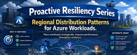
Proactive Reliability Series — Article 2: Regional Distribution Patterns for Azure Workloads
Public cloud platforms — including Microsoft Azure — are built on three foundational principles that distinguish them from traditional on-premises infrastructure: Elasticity: The platform can automatically expand and contract resource capacity in response to demand. Capacity is not statically provisioned; it is drawn from a shared pool and released when no longer needed. Scaling: Workloads can scale horizontally (adding more instances) or vertically (increasing instance size) on demand, without pre-procurement of physical hardware. Consumption-based billing: Customers pay for what they use, when they use it. Cost is proportional to resource consumption, not to physical capacity reserved in advance. These principles are properties of the platform, not of any single location. Microsoft Azure Cloud is not a single region — it is a globally distributed platform comprising dozens of regions across every major geography, interconnected by a private backbone network. When an organisation deploys to Azure, it is deploying into this global system; the choice of which region or regions to use is based on an organizational strategy and architectural decision. Using a single Azure region is a valid choice in many scenarios, but it has to be a deliberate architecture decision, not an omission. Why Multi-Region? Microsoft Azure CTO Mark Russinovich summarises the case for multi-region in Achieve agility and scale in a dynamic cloud world: organisations that span multiple regions gain scalability and flexibility (choosing from the full Azure region portfolio, including differentiated pricing, AI capabilities, and deployment options), resilience and availability (reducing the impact of regional disruptions through multiple backup and recovery options), and performance and reduced latency (serving users from infrastructure that is geographically closer to them). The post's closing recommendation — "leverage Azure as a cloud platform, not a datacenter region" — makes explicit what the multi-region decision ultimately is: a choice to treat the platform's global footprint as an asset, not a constraint. Mark Russinovich — Achieve agility and scale in a dynamic cloud world (Microsoft Azure, September 2024) This article also does not argue whether to adopt a multi-region strategy — that is a business and risk decision. It describes what the options are: the available regional distribution patterns, the forces each resolves, and the trade-offs each accepts. Regional workload distribution is not simply an application-level decision — it is an organisational one. It shapes how a company scales its cloud presence, manages cost and operational complexity across a growing portfolio, meets data residency and regulatory obligations, and positions itself to respond to changing conditions. Multi-region is often a necessity, not a free choice: growth ambitions, compliance requirements, or risk obligations may demand it. But necessity does not determine form. These patterns define the decision space: whether operating across multiple regions is warranted at all, and if so, which structural arrangement fits the organisation's scale, objectives, and operational capability. Several patterns are adapted from Gregor Hohpe's multi-cloud strategy patterns, originally described in Multi Cloud Architecture: Decisions and Options and further elaborated in Multi-cloud: From Buzzword to Decision Model. Important This is an unofficial guide to regional distribution patterns for Azure workloads. It is not an official Microsoft publication and is not officially supported, endorsed, or maintained by Microsoft. All descriptions and recommendations are based on publicly available Azure documentation and general distributed systems principles. Always refer to official Azure documentation and the Azure Well-Architected Framework for authoritative guidance. The Risks and Opportunities Pattern selection is a direct response to specific risks or solution quality requirements. Before evaluating patterns (options), it is necessary to understand what risks are actually relevant — infrastructure faults, capacity constraints, service coverage gaps, and compliance or business obligations — and what their scope of impact is. Azure infrastructure is complex and distributed. While Microsoft invests heavily in reliability, faults can and do occur across a wide range of blast radii — from a single compute instance at the narrowest end, through Availability Zone and regional failures, to global service disruptions at the widest. The appropriate pattern is the one that reduces unacceptable risks to a tolerable level. The Azure Well-Architected Framework — Reliability pillar recommends Failure Mode Analysis (FMA) as the structured technique for enumerating failure modes, assessing their impact, and identifying mitigations before they are needed in production. The fault types below are the infrastructure-layer inputs to that analysis. For a detailed breakdown of each fault type — including likelihood analysis, real-world incident examples, and detection guidance — see Proactive Reliability Series — Article 1: Fault Types in Azure. Risk Catalog (Sample) The following is a representative sample of risks relevant to regional workload distribution decisions, not an exhaustive catalogue. Not all entries are infrastructure faults — some represent business and compliance obligations. The Category column identifies the type of each risk. Likelihood values are relative planning heuristics to help prioritise resilience investments — they are not statistical probabilities and do not represent Azure SLA commitments. Risk Category Blast Radius Likelihood Primary Mitigation Service Fault (Region) Infrastructure Fault Single service within a region Medium Region redundancy Region Fault Infrastructure Fault Regional degradation or full regional loss (partial-to-full region impact) Low Region redundancy; cross-region failover Network POP Location Fault Infrastructure Fault Network colocation site (affects connectivity, not compute) Low ExpressRoute Metro (dual peering locations); network path redundancy Service Fault (Global) Infrastructure Fault Worldwide or multiple regions simultaneously Very Low Accept risk; use alternative service if downtime is intolerable Regional Service Capacity Constraint Infrastructure Capacity Single region (required capacity unavailable — whole service or specific SKU — at failover time or sustained shortage) Low Region redundancy; Capacity Reservations; Hot Standby; alternative region Service Regional Unavailability Infrastructure Fault Single region (desired service not offered in that region) Low Deploy to a region where the service is available Geopolitical Risk Compliance One or more regions (regulatory or political mandate to relocate) Low Portable pattern; pre-validated alternative region Sustainability Constraint Compliance One or more regions (sustainability targets unachievable in current region) Low Portable pattern; relocate to region with required sustainability profile The Patterns While there could be many ways to distribute workloads across Azure regions, the following patterns represent the most common and widely applicable approaches. Each pattern is a structural topology that defines how workloads are deployed and how they respond to Risks and Quality Requirements. The patterns are not mutually exclusive — they can be combined or layered to meet specific requirements. The following patterns describe the principal ways workloads can be distributed across Azure regions. Patterns 1-3 are described and found very often, while patterns 4-5 are less common but still important to consider. The table below summarises the patterns, their intent, and the primary driver for their adoption. # Pattern Intent Primary Driver 1 Single All resources in one Azure region; AZ redundancy optional Simplicity; cost; data residency constraints 2 Failover Primary region serves traffic; secondary region is a cold or hot standby for DR Business continuity 3 Parallel Same workload deployed to multiple regions simultaneously; all active Continuous availability; zero-downtime failover 4 Segmented Services or service portfolio distributed across regions by BU, LOB, tenant, or data residency Isolation; sovereignty; independent release cadence 5 Portable Full portability; workloads can be relocated between regions without application changes Operational flexibility; on-demand relocation 1. Single Region Pattern Pattern Name: Single Region Workload Distribution Classification: Regional workload distribution Scope: Workload — applies to a single application or service deployment, Workload (Application) Portfolio Intent: Deploy all workload resources in one Azure region; Context: A workload is being deployed to Azure and must decide how many regions to use. The business impact of a regional outage has been assessed — either as tolerable within the workload’s criticality tier, or as not applicable because data sovereignty constraints prohibit cross-region replication. The team needs to treat Single Region as an explicitly chosen architecture, not an omission. Problem: Every additional Azure region adds infrastructure cost and workload integration complexity due to the introduced network latency. Not all workloads justify this overhead. The question is not “should I always use multiple regions?” but “when is a single region the correct and explicitly chosen answer, and when does adding a second region produce risk-reduction that justifies the cost?” Forces: The workload’s risk profile does not justify cross-region redundancy: the business impact of a regional outage is tolerable, data sovereignty rules prohibit cross-region replication, or reliability requirements are fully met within a single region with Availability Zone redundancy. The cost of multi-region infrastructure produces no corresponding risk-reduction return for this workload. Solution Place all compute, data, and networking resources in a single Azure region. Apply Availability Zone redundancy within that region for protection against datacenter-level failures. Formally accept region-level risk as within tolerance for this workload’s criticality tier — this is a deliberate architecture decision, not an omission. Implementation: Enable Availability Zones for all production resources where supported. Use Azure Infrastructure Resiliency Manager (AIRM) to validate zone-redundancy posture across the workload. Document the risk-acceptance decision explicitly at the application level. Consequences Benefits: Lowest cost and operational footprint of all patterns. No cross-region routing, replication lag, or failover coordination complexity. Simplest deployment pipeline, observability surface, and incident response. Liabilities: No mitigation for any region-level fault — full workload loss on regional failure. Data concentrated in one geography; no cross-region durability without explicit configuration. No pre-deployed capacity in an alternative region. Risk posture: Risk Assessment Region Fault ❌ Primary unaddressed risk — partial degradation or full regional failure has no cross-region recovery path; accept or upgrade pattern Service Fault (Region) ❌ Regional service failures have no cross-region alternative Regional Service Capacity Constraint ❌ No alternative region available; both on-demand failover provisioning and sustained SKU shortages have no mitigation path Network POP Location Fault ✅ Addressable within this pattern via ExpressRoute Metro (dual peering locations in the same metro); does not require a multi-region distribution change Known Uses Development and test environments; Bronze- or Non-Critical-tier workloads; workloads with strict data residency constraints that prohibit cross-region replication; proof-of-concept and time-limited deployments. See Azure Services - Sample Multi-Region Capabilities Pattern Mapping for how individual Azure services implement this pattern. 2. Failover Pattern (Primary + Standby Region) Pattern Name: Failover Workload Distribution Also Known As: Active-Passive, Disaster Recovery (DR), Business Continuity and Disaster Recovery (BCDR) Classification: Regional workload distribution, Application Design, Platform/Infrastructure Design, Disaster Recovery Scope: Workload — an application and infrastructure design pattern that requires both layers to work in tandem; Workload (Application) Portfolio Intent: Recover from a regional disaster or other longer duration region outage by designating a primary region to carry all production traffic and a standby region to absorb that traffic upon primary region failure. The typical quality attribute metrics that govern its design are RTO (Recovery Time Objective — maximum tolerable downtime), RPO (Recovery Point Objective — maximum tolerable data loss), and MTTR (Mean Time To Recovery — the observed average recovery time, measured through drills and real incidents, that validates whether the RTO target is achievable in practice). Context: A workload must survive region-level failures, but the architectural complexity of running two fully active deployments simultaneously — with multi-region write-conflict resolution — is not justified. The business can tolerate a bounded recovery time and, depending on the sub-variant chosen, a bounded data loss window. Problem: A fully active multi-region deployment (Parallel pattern) introduces multi-region write-conflict complexity that the application cannot or need not absorb. The Failover pattern trades continuous availability for single-writer simplicity: one region is active, one is standby, and recovery is bounded by RTO/RPO targets. The sub-variant choice (Cold / Warm / Hot) then determines how much cost is invested in standby readiness — from minimal (~1.1×) to near-full duplication (~2×) — based on how fast recovery must be. Forces: A single active write region is required — multi-region write-conflict resolution adds unacceptable consistency risk or development complexity. RTO and RPO targets must be met, but budget constrains how pre-warmed the standby region can be, driving the Cold / Warm / Hot sub-variant selection. Regional Service Capacity Constraint in the standby region is a residual risk for Cold and Warm sub-variants — the standby may fail to scale at failover time unless capacity is pre-reserved. Solution Designate one region as primary (all production traffic under normal conditions) and a second as standby (no production traffic until failover). The standby’s readiness level — the sub-variant choice — is determined by the RTO/RPO requirements and cost envelope. Replication from primary to standby is continuous; failover is triggered manually or automatically when the primary becomes unavailable. Note on "Active-Passive": This pattern is often called Active-Passive in Microsoft documentation. That framing is accurate at the traffic level (one region active, one passive), but it can obscure the architectural intent. The Failover label here emphasises the capability being purchased: the ability to redirect the entire workload to a pre-designated region when the primary is unavailable. Implementation: The key design decision is how ready the standby is at the moment it is needed. Three sub-variants define this readiness spectrum: Sub-variant Secondary state Cost multiplier Cold Standby No running compute; data either in scheduled backups or continuously replicated ~1.1–1.5× Warm Standby Reduced-scale compute running; data continuously replicated ~1.5–1.8× Hot Standby Full-scale compute running; data continuously replicated ~2× Cold Standby — No compute is running in the standby region under normal conditions. Cold Standby covers two positions within this state, differing in how the data layer is protected: Backup/Restore: Data is backed up or geo-replicated on a scheduled basis. On failover, infrastructure must be deployed from scratch and data restored before traffic can be redirected. RTO is measured in hours; RPO equals the interval between the last backup cycle and the failure event. Data-layer live, compute stopped: Core infrastructure (networking, identity, data tier) is kept running with continuous replication to the standby region; compute is stopped or scaled to zero. On failover, compute is started and scaled up to meet full load. RTO is typically 15–60 minutes; RPO is bounded by async replication lag rather than backup interval. Both positions share the defining characteristic of Cold Standby: no production-equivalent compute running in the secondary region under normal conditions. The difference is the investment in keeping the data layer live, which reduces both RTO and the data loss window at a modestly higher steady-state cost. Warm Standby — The standby region runs a scaled-down but functionally complete version of the workload. Traffic is not routed there under normal conditions. On failover, the secondary scales up and traffic is redirected. A brief scale-out lag occurs before the secondary absorbs full traffic; the running environment eliminates cold-start delay. Hot Standby — The standby region runs a full, production-equivalent deployment — same compute capacity, same configuration — but receives no traffic under normal conditions. Data is continuously and near-synchronously replicated. Failover is fast and often automated because no scale-up is required. Consequences Benefits: Enables recovery from region-level faults at a fraction of Parallel pattern cost. Flexible cost-vs-RTO trade-off across Cold / Warm / Hot sub-variants. No multi-region write-conflict complexity; single active write region throughout normal and recovery operation. Liabilities: Cold and Warm standby introduce meaningful RTO (minutes to hours). Replication lag creates a data loss window (RPO > 0) at the moment of failover. The failover path is the least-exercised code path — untested recovery inflates actual RTO. Failover is often neglected and not properly and regularly tested - this leads toward a fear to execute failover when needed (and it is not only full region disaster). Risk posture: Risk Assessment Region Fault ⚠️ Primary driver; standby region absorbs traffic on full regional loss, but partial regional degradation may not trigger automated failover. RTO depends on sub-variant Regional Service Capacity Constraint ⚠️ Cold/Warm Standby are exposed to both on-demand provisioning failure and sustained SKU shortages — mitigated by Capacity Reservations or Hot Standby Service Fault (Region) ✅ Standby region provides an alternative deployment for regional service failures Service Regional Unavailability ⚠️ Secondary region must be verified for full service parity at design time — absent services block failover regardless of compute readiness Known Uses Business-critical workloads with defined RTO/RPO targets that cannot accept region-level risk but do not require continuous multi-region availability; workloads with single-writer data models where multi-region write-conflict resolution is unacceptable; regulatory environments where a designated recovery region must be pre-approved. See Azure Services - Sample Multi-Region Capabilities Pattern Mapping. 3. Parallel Workload Distribution (Simultaneous Active Deployment) Pattern Name: Parallel Workload Distribution (Simultaneous Active Deployment) Also Known As: Active-Active Classification: Regional workload distribution, Application Design Scope: Workload — an application-level design pattern; requires the application and its data layer to be explicitly designed for concurrent multi-region operation, Workload (Application) Portfolio Intent: Deploy the same workload simultaneously to two or more Azure regions, all serving production traffic. Context: Two independent drivers lead to this pattern, often simultaneously: the workload serves geographically distributed users who require regional proximity to meet latency targets, and the availability tier demands zero-downtime through region-level failures. A single deployment point cannot satisfy both. Manual failover timelines, standby region promotion, and RPO windows are incompatible with the required availability tier. This pattern is the mandated baseline for Mission-Critical workloads in the Azure Well-Architected Framework. Problem: Passive standby and failover mechanisms introduce recovery time and data loss windows that are incompatible with high-availability targets (e.g. 99.99%+). Meeting both demands requires all regions to be equal active participants — not a primary and a standby. But this demands that the data layer either supports concurrent writes across regions, relies on continuous cross-region replication with a defined consistency model, or is predominantly read-heavy — and that pre-provisioned capacity is maintained in every active region at all times. Forces: Regional failure must produce zero downtime — manual failover timelines cannot satisfy the availability target. Traffic originates from geographically distributed users who require regional proximity to meet latency SLAs. Availability targets (e.g. 99.99%+) eliminate passive standby as a viable option. The application can tolerate eventual consistency or is read-heavy enough that multi-region write complexity is manageable. Once multi-region data access is solved, every region's compute actively serves production traffic — the capacity that Failover Hot Standby holds idle is fully utilised; the cost multiplier buys active production capacity, not idle insurance. Solution Deploy the workload identically to two or more Azure regions. Route production traffic to all active deployments simultaneously via a global load balancer — under normal conditions, each user is directed to the nearest active region, minimising latency. On regional failure, the load balancer automatically rebalances traffic to the remaining healthy regions — no manual promotion, no scale-up delay. All regions are equal peers; there is no concept of primary and secondary. Implementation: Deployment Stamps are commonly used to implement Parallel at scale — multiple active regional instances behind global routing. See Deployment Stamps pattern — Azure Architecture Center. Stamps are not exclusive to Parallel: the same approach can also support Segmented and, in some designs, Failover. Regions active: 2+ (all serving production traffic simultaneously). Typical cost multiplier: ~2–3×. Microsoft guidance — Mission-Critical workloads: The Azure Well-Architected Framework’s Mission-Critical design methodology explicitly advises active-active multi-region deployment as the baseline for workloads targeting 99.99% availability or higher. The application design guidance states: “The application must be able to withstand regional and zone failures. It must be deployed in an active/active model so that the load is distributed among all regions.” The regions and availability zones guide reinforces this: “Mission-critical workloads should use both multiple availability zones and multiple regions.” The WAF Reliability pillar describes active-active as the mechanism to achieve zero downtime, noting it is “ideal for mission-critical workloads that require uninterrupted availability.” Consequences Benefits: Regional failure triggers automatic traffic rebalancing — no manual failover, no service interruption. Lowest RTO of all patterns; zero-downtime regional failure recovery. On regional failure, remaining regions absorb redirected traffic immediately — if at capacity, the workload degrades under load rather than failing completely; degraded performance is a fundamentally better failure mode than an unavailability window. Serves geographically distributed users within latency bounds simultaneously from the nearest active region. Compute deployed per region actively generates production value under normal conditions — the nominal cost multiplier buys utilised capacity, not idle standby insurance. Liabilities: Highest nominal cost (~2–3×) — though compared to Failover Hot Standby (~2×), the effective cost of resiliency is lower: every unit of deployed capacity actively serves production traffic rather than sitting idle as insurance. Requires the application to support multi-region writes or be predominantly read-heavy; write-conflict resolution is an application responsibility. Multi-region CI/CD, distributed observability, and write-conflict handling add steady-state operational overhead — but eliminate the failure-event burden: no failover procedure, no drill schedule, no risk of untested recovery paths inflating actual RTO. Risk posture: Risk Assessment Region Fault ✅ Primary driver; automatic traffic rebalancing handles both partial regional degradation and full regional loss — no promotion or manual steps required Service Fault (Global) ⚠️ No regional workload distribution pattern mitigates a truly global service disruption — but the impact is often partial: only specific SKUs, tiers, or versions of a service may be affected, leaving workloads on unaffected variants operational. Where the risk is intolerable, the mitigation is service substitution: switching to an alternative Azure service with equivalent functionality, or a third-party / self-hosted equivalent Service Fault (Region) ✅ Automatic rebalancing redirects traffic away from the affected region without manual failover Regional Service Capacity Constraint ✅ All regions are pre-deployed and running; no on-demand capacity provisioning required at failover time — if a region fails and remaining regions reach capacity limits, the result is degraded performance under load, not complete unavailability Known Uses Mission-Critical workloads targeting 99.99%+ availability per WAF guidance; globally distributed consumer applications where regional proximity is a primary SLA requirement; financial trading and payment platforms where any recovery window is commercially unacceptable; real-time communication and streaming services where failover lag degrades the user experience. See Azure Services - Sample Multi-Region Capabilities Pattern Mapping. 4. Segmented Workload Distribution (Regional Distribution by Boundary) Pattern Name: Segmented Workload Distribution Also Known As: Deployment Boundaries, Regional Portfolio Allocation Classification: Regional workload distribution (portfolio scope) Scope: Portfolio / Organisation — a structural pattern for distributing a portfolio of workloads, tenants, or business units across regions; individual workloads within a segment may independently apply any other pattern Intent: Assign each Azure region a distinct, non-overlapping responsibility boundary so that regions are differentiated by ownership and isolation rather than by redundancy. Context: A portfolio of workloads, a multi-tenant application, or a multi-LOB organisation must distribute services or data across regions. The drivers include regulatory boundaries, tenant isolation, blast-radius containment, or operational independence — not simply increasing redundancy. Individual boundaries within the portfolio have materially different criticality tiers, release cadences, and recovery requirements. Problem: Running a second Azure region purely as a Failover standby generates ongoing cost without delivering business value under normal conditions. How can an organisation operate multiple regions so that every region carries real production workload, the cost is justified by utilisation rather than insurance alone, and each region's scope is independent enough that faults and changes in one area do not propagate to others? Forces: Regulatory, sovereignty, or compliance obligations drive geographic boundary placement — but strict data residency that prohibits cross-boundary replication also prevents the cross-region recovery that makes Segmented cost-efficient; a boundary whose data cannot leave its region can only recover within that region (Single Region posture), regardless of what neighbouring segments deploy. Independent release cadences, lifecycle autonomy, and scaling requirements across services, tenants, or business units conflict with coupled shared-infrastructure deployments. Blast-radius containment requirements prevent a single fault or bad deployment from affecting the entire portfolio. This pattern does not answer how each boundary recovers; that choice is made independently per boundary using Single, Failover, or Parallel. Solution Define non-overlapping responsibility boundaries and assign each boundary to a region. Each region owns its boundary exclusively — no region is a replica of another. Each boundary independently selects its own recovery posture (Single, Failover, or Parallel) based on its own criticality and requirements. The key structural advantage is region reuse: because multiple regions are already deployed and carrying real production load, each region can simultaneously serve as the Failover standby or Parallel peer for a neighbouring boundary — the same infrastructure investment delivers both production utilisation and recovery capability. This dual-purpose reuse is only available where cross-boundary data replication is permitted; where strict data residency prohibits it, each boundary must treat itself as isolated and plan recovery within its own region. Implementation: The boundary can be defined at different scopes: Within one application: tenants, markets, release rings, or data partitions assigned to different regions. Across a service portfolio: different applications, domains, or business capabilities intentionally placed in different regions. Segmentation axis Example Geography / data residency EU services and data in West Europe, US services and data in East US Business unit / LOB Finance portfolio in Region A, HR portfolio in Region B Customer tier Premium customer workloads in dedicated region(s), standard in shared region(s) Release ring Ring 0 workloads in Region A, Ring 1 workloads in Region B Scale tier High-volume service groups in larger regions, low-volume groups in smaller regions Consequences Benefits: A fault in one boundary is contained to that region and does not propagate to adjacent boundaries. Each boundary independently selects its own recovery posture, cost level, and compliance configuration. Supports independent release cadences, scaling policies, and lifecycle management per boundary. Region reuse: already-deployed regions carrying production load can simultaneously serve as Failover standby or Parallel peer for neighbouring boundaries — the infrastructure investment delivers both production utilisation and recovery capability without paying for idle standby capacity. Liabilities: Cross-boundary dependencies — shared identity, shared data stores — undermine isolation guarantees and must be minimised by design. Governance overhead scales with the number of active boundaries; requires a formal boundary ownership model to remain manageable. Risk posture: Risk Assessment Service Fault (Region) ⚠️ Fault is contained to the affected boundary; adjacent boundaries continue operating — within-boundary recovery depends on that boundary’s posture Region Fault ⚠️ Only the boundary hosted in the affected region is impacted — RTO/RPO is determined by that boundary's individual recovery posture Regional Service Capacity Constraint ⚠️ Only the boundary in the capacity-constrained region is affected; other boundaries continue operating — mitigation depends on the boundary's own topology (Failover or Parallel provides alternatives; Single does not) Geopolitical Risk ✅ Boundaries can be relocated independently; the rest of the estate continues operating while the affected boundary is relocated Service Regional Unavailability ✅ Each boundary can be independently placed in a region where all required services are available Known Uses Geo-distributed enterprise application portfolios; organisations with a federated business model where autonomous business units operate independently with their own release cadence, cost accountability, and compliance obligations; SaaS platforms with tenant-per-region isolation; regulated financial and healthcare services with strict data residency by jurisdiction. See Azure Services - Sample Multi-Region Capabilities Pattern Mapping. 5. Portable Workload Distribution (Full Abstraction) Name: Portable Workload Distribution (Full Abstraction) Also Known As: Region-Agnostic Deployment, Cloud-Neutral Deployment Classification: Operational property (applicable to any structural pattern) Scope: Workload — a design property of an individual workload; composable with any structural pattern at either workload or portfolio scope Intent: Fully abstract the workload from the underlying Azure environment so it can be relocated to any Azure region at any time without modifying application code or configuration. Context: A workload is subject to compliance obligations — regulatory, geopolitical, or sustainability — that may require region relocation on short notice. Or the workload's operational requirements include the ability to optimise cost, respond to capacity constraints, or avoid service unavailability across regions. Portability is not the default outcome — it requires an explicit design decision and sustained engineering investment. Without that intent, the default is a workload that is structurally bound to its current region. Problem: Without a portability investment at design time, a relocation trigger forces significant rearchitecting under pressure rather than as a controlled migration. Forces: Compliance obligations — regulatory, geopolitical, or sustainability — may require relocation on short notice; deferring the portability decision converts a design choice into a forced rearchitecting event at the worst possible time. Data portability is the hardest dimension: scheduled backup/restore, continuous replication, and live migration each introduce cost, complexity, and consistency trade-offs that must be accepted at design time. Relocation may be temporary or permanent; the architecture must support both without distinguishing between them at deploy time. A port may be partial (subset of workloads) or full (entire estate); partial porting creates transient cross-region dependencies that must be explicitly designed for and eliminated as the migration progresses. Solution Select and implement a data portability mechanism — continuous replication, backup/restore, or live migration — whose cost, RPO, and operational model are explicitly accepted at design time. The target region is not fixed at design time — it is chosen when a trigger event occurs, and can be any eligible region. The workload stays in its current region under normal conditions and relocates only when a trigger event warrants it. Implementation: Portable is a layered property, not a separate structural topology. The underlying structural topology (Single, Failover, Parallel, or Segmented) determines traffic routing and redundancy; Portable governs whether that topology can be instantiated in a different region without application changes. The cost multiplier adds toolchain and abstraction overhead on top of the chosen structural topology. Data portability — the critical path: Compute portability is straightforward — container images and environment-agnostic configuration are standard practice. Data portability is the harder problem. Two mechanisms make it achievable: Continuous replication: The data layer replicates to the target region at all times, so the data is already present when a relocation is triggered. Azure Cosmos DB with multi-region writes, Azure SQL Database geo-replication, and Azure Storage geo-redundancy (RA-GRS/RA-GZRS) are common implementations. Continuous replication minimises RPO but adds steady-state cost. Automated data migration: A codified and continuously tested migration pipeline moves data to the target region at relocation time. Appropriate when continuous replication cost is not justified, or when the data tier does not support native geo-replication. The migration must be automatable, testable in isolation, and fast enough to satisfy the workload’s RTO for the trigger event. Port modes: Partial vs. Full A port — the act of relocating a workload using the Portable pattern — can be scoped in two ways: Partial port: A subset of workloads is relocated to the target region while others remain in the source region. This creates transient cross-region dependencies — service calls, data access, shared identity — between moved and not-yet-moved workloads. These dependencies must be explicitly designed for, monitored for latency and failure, and eliminated progressively as the migration advances. Partial porting is the natural execution mode for large estates where simultaneous full relocation is operationally infeasible. Full port: All workloads are relocated to the target region, either simultaneously or in a planned sequence that keeps cross-region dependencies only for the duration of each step. A full port is a long-term, intentional change of primary region. It is fundamentally different from a Failover event: Dimension Failover Full Port (Portable) Intent Quick recovery and return to primary region when resolved Permanent change of the region Duration Temporary — primary is restored after the event Long-term or permanent — target becomes the new primary Return Expected — traffic and workloads revert to original region Not expected — no return is planned Driver Region fault, outage, or transient unavailability Compliance, cost, sustainability, or strategic decision Transition Time Aiming RTO Transition can take weeks or months (but it can be designed to serve the Failover purpose and meet RTO and RPO requirements) Transition disruption Minimal — automated or semi-automated failover Managed — gradual migration with a cross-region dependency period The Portable pattern must support both modes and both scopes. A workload that can only be relocated as an atomic all-or-nothing operation has limited practical utility; a workload designed for incremental partial porting is far more executable at scale. Consequences Benefits: Workload can relocate to any Azure region without application changes — eliminates region lock-in. Target region is determined at the time of the trigger, not at design time — unlike Failover's fixed designated standby, the destination can be any eligible region and can change between port events as requirements evolve. Primary architectural mitigation for compliance-driven relocation risks (Geopolitical Risk, Sustainability Constraint). Relocation can be temporary (workload returns after trigger resolves) or permanent — the architecture supports both without distinguishing between them. Liabilities: Portability is costly to establish and maintain; data portability and the abstraction layer add ongoing engineering and toolchain overhead. Data portability is the hardest and most underestimated engineering challenge — relocating compute is straightforward; relocating live data at acceptable cost, latency, and consistency is not. Introduces dependency on the abstraction toolchain — portability conventions must be actively enforced as engineering standards; without governance, individual implementation decisions erode them over time. Risk posture: Risk Assessment Geopolitical Risk ✅ Primary driver — region-agnostic workload relocates to a compliant region; unportable workloads face forced migration under time pressure Sustainability Constraint ✅ Workload moves to a region with the required sustainability profile without application-level changes Regional Service Capacity Constraint ✅ Workload can be relocated to an alternative region with available capacity — addresses both on-demand provisioning failure and sustained shortages Region Fault ✅ Workload can be relocated to an alternative region; recovery speed depends on data portability readiness Service Regional Unavailability ✅ Workload can be redirected to any region where required services are available — portability removes the fixed-region constraint Known Uses Workloads subject to data sovereignty or geopolitical obligations that may require region relocation on regulatory notice; sustainability-committed workloads that may need to move to regions with a lower carbon intensity; workloads in rapidly expanding organisations that need to follow business growth into new geographies without rearchitecting. Several patterns are adapted from Gregor Hohpe's cloud strategy patterns: Multi Cloud Architecture: Decisions and Options — Architect Elevator. See Azure Services - Sample Multi-Region Capabilities Pattern Mapping. Related Patterns Portable vs. Failover — Both result in a workload running in a different region, and a full port and a Hot Standby activation look nearly identical at execution time. The distinctions are fundamental: Failover is a topology (one region is permanently designated as standby); Portable is a property that can be layered on top of any topology. Failover requires a fixed secondary region to be designated at design time — the target is known, pre-provisioned, and not interchangeable. Portable has no fixed target: the destination region is chosen at the time of the trigger, can be any eligible region, and can differ between port events as compliance, cost, or operational requirements change. Failover is triggered by an unplanned disruption and is temporary — the expectation is to return to the original primary when the event resolves. A Portable port is triggered by a deliberate decision and is permanent — the destination becomes the new primary with no planned return. A Failover workload can also be Portable, applying both patterns simultaneously: Failover handles unplanned disruptions; Portable handles deliberate relocation decisions. They are orthogonal — not alternatives. From Patterns to a Cloud Growth Strategy The patterns in this article show that regional distribution is not a single decision — it is a spectrum of options, each with a different cost, complexity, and risk mitigation profile. The patterns are not mutually exclusive: a portfolio — or even a single workload — may combine multiple patterns to achieve its reliability, compliance, and operational goals. Having the full range of patterns available does not answer the harder question: which patterns are right for your organisation, which applications need them, and what will it take to get there? That is a strategy question — and it requires a deliberate answer. Most organisations today operate their workloads in the Single Region or Failover pattern. Transitioning from that baseline to Parallel, Segmented, or Portable distribution is not an infrastructure change — it is a programme of work that requires investment justification, architectural readiness, and a governed execution plan. A Cloud Growth Strategy based on regional workload distribution starts by defining the organisation's objectives: what reliability targets must be met, which compliance or sovereignty constraints apply, what operational scale is planned, and where the current estate falls short. From those objectives it derives what the regional footprint should look like for this organisation — not as a generic best practice, but as a concrete commitment about which patterns apply to which parts of the portfolio, at what pace, and at what cost. Conclusion Azure's global footprint makes regional workload distribution a choice for every workload — but not a requirement for all of them. The decision starts with risk: the Risk Catalog identifies which fault types and capacity or compliance constraints are actually relevant to the workload, and what blast radius each carries. From that foundation, five patterns emerge — Single Region, Failover, Parallel, Segmented, and Portable — each resolving a distinct set of forces at a different cost and complexity point. Real Azure services rarely fit one pattern cleanly; the service examples in this article illustrate how capability gaps, consistency models, and replication architectures constrain which patterns are structurally achievable. Translating this into organisational practice requires a deliberate Cloud Growth Strategy: classify applications by criticality, assess their suitability for each pattern against their current state, and produce a governed distribution map that is maintained as the portfolio and platform evolve.Choosing two-zone and three-zone patterns for zone-resilient Azure workloads
This article complements our Advancing Reliability series post, Two zones or three? A design framework for zone-resilient Azure workloads. Together, they provide guidance on both the considerations and deployment patterns for zone-resilient Azure workloads. Purpose This article helps customers evaluate Azure workload components and choose zone-resilient patterns that meet their requirements during a single-zone failure. The goal is to identify where two zones can meet workload requirements, where three zones are required, and where service-managed zone redundancy is the right approach. Important: This guidance is a decision framework, not a service support matrix. Availability zone behavior varies by Azure service, SKU, tier, region, and configuration. Always validate the selected design against the relevant Azure reliability guidance and test the workload's actual failure behavior before finalizing the architecture. Zone resiliency helps protect against the loss of a single availability zone. It does not protect against a full-region outage. For mission-critical workloads or workloads with strict disaster recovery requirements, evaluate whether the workload also requires a multi-region design. Availability zones are separate groups of datacenters within an Azure region. Each availability zone has independent power, cooling, and networking infrastructure. Azure services that support availability zones generally expose support through zone-redundant or zonal deployment models. Key takeaways Evaluate zone patterns at the workload component level, not only at the whole-workload level. Many workloads can meet single-zone failure objectives by using two zones for some components and three zones only where component requirements demand them. For the single-zone failure mode, two-zone and three-zone patterns can both meet resource availability objectives when remaining capacity and failover behavior are validated. Use service-managed zone redundancy when it meets workload requirements. Use two zones when the component can meet its availability, durability, capacity, performance, and operational requirements across two zones. Use three zones when a component requires the additional zone for post-failure capacity, data durability, replication topology, quorum, leader election, or operational margin. Balance cost and operational complexity after defining the workload's resiliency objective. Do not assume that two zones are always cheaper or that three zones are always required. Zone-redundant and zonal deployment models Zone-resilient designs depend on the deployment model used by each Azure service. Zone-redundant resources are distributed or replicated across multiple availability zones. Azure manages replication, request distribution, and failover behavior for the service. Where available and aligned to workload requirements, zone-redundant resources should be preferred, especially for production deployments. Zonal resources are pinned to a specific availability zone. A zonal resource is isolated from failures in other zones, but it is not automatically resilient to a failure in its own zone. To make a zonal service resilient, customers need to deploy separate instances across multiple zones and design the workload to route traffic, replicate data, detect failures, and recover. Some Azure services offer both zonal and zone-redundant deployment options, while others may be zone-resilient by default. In some cases, availability zone support requires additional configuration, service modification, or redeployment. Support can also vary by region, SKU, tier, or service configuration. Before choosing a deployment model, review the service-specific reliability guidance and availability zone support matrix to understand the options and requirements for your scenario. Primary decision dimensions Current Azure Well-Architected guidance emphasizes deploying production workloads across two or more failure domains to improve resiliency to failures within a single failure domain. In Azure regions that support availability zones, those failure domains are exposed as availability zone boundaries. When deciding whether a component should use two zones, three zones, or service-managed zone redundancy, evaluate three dimensions: Resource availability: For the single-zone failure mode, two-zone and three-zone patterns can both meet resource availability objectives when the remaining zone or zones can support the required operating state and failover behavior. The additional zone in a three-zone design does not by itself make the component resilient to more than one zone failure within the same region. Data consistency and durability: Stateful components might require three zones when data durability, replication topology, quorum, consensus, leader election, or split-brain prevention depends on a third failure domain or third replica placement. Cost and capacity: For the same post-failure performance target, a two-zone design can require more recovery capacity than a three-zone design. Cost optimization should be evaluated after the resiliency objective is defined. If more than one availability zone is unavailable in the same region, the concern can become regional rather than only workload-specific because foundational regional services require at least two surviving availability zones for continued regional availability. Workloads with requirements beyond a single-zone failure should evaluate disaster recovery or multi-region design separately. Common workload components can be grouped as follows: Component category Typical zone decision Stateless resources that support networking or application code and do not store persistent data Two-zone or three-zone flexibility, based on remaining capacity, routing, latency, and operational requirements. Stateful resources that use node-based quorum, consensus, or leader election Three zones, a third failure domain, or a product-specific witness pattern is commonly required to avoid split-brain or quorum-loss scenarios. Critical data stores that require three replicas for the highest durability targets Three-zone replication might be required to support the intended durability level, such as eleven-nines-style durability targets. Validate service-specific claims. Other stateful resources Two-zone, three-zone, or service-managed patterns can be valid depending on service behavior, recovery time objective (RTO), recovery point objective (RPO), durability, failover, and recovery requirements. Component-level decision framework Walk through the workload by critical flow and component. For each component, determine whether service-managed zone redundancy applies, whether a two-zone pattern can meet the component's single-zone failure objective, or whether three zones are required. Component question What to evaluate Decision guidance Is zone resiliency managed by the Azure service? Confirm whether the service provides zone-redundant or zone-resilient behavior through a supported configuration, SKU, tier, or replication mode. Use service-managed zone redundancy when it meets workload requirements. Do not force a two-zone or three-zone customer-managed design onto services where Azure manages placement and failover internally. Is the component stateless or easily replaceable? Evaluate routing, health probes, scale-out behavior, post-failure capacity, deployment automation, monitoring, and recovery steps. Two zones can often meet requirements for stateless or easily replaceable components when the remaining zone can support the required degraded or full operating state. Use three zones when capacity distribution or operational requirements justify the added design and testing scope. Does the component store durable state? Evaluate replication mode, data durability, consistency, RTO, RPO, failover behavior, recovery behavior, and service-specific support. Use the pattern that satisfies the data protection and recovery requirements. Three zones might be required when the storage or data service requires an additional zone for durability, triple-replica placement, replication topology, or recovery behavior. Does the component use quorum, consensus, or leader election? Validate replica placement, majority behavior, witness or tie-breaker design, leader election, split-brain prevention, recovery, and failback. Do not assume that three replicas across two zones are sufficient. Three zones, a third failure domain, or a product-specific witness pattern might be required to tolerate a zone loss safely. Is the component latency-sensitive? Define latency and throughput thresholds, test candidate zone pairs with realistic protocols and configuration, and identify which paths are actually latency-sensitive. Two zones can be appropriate for latency-sensitive synchronous paths that use tested placement. Logical zone numbers can map to different physical zones across subscriptions, so validate zone mapping when selected zone pairs matter. What capacity must remain after one zone fails? Define the required post-failure operating state for the component: degraded but acceptable, full baseline, or standby recovery. Choose the zone pattern that can satisfy the required post-failure operating state. Two zones can meet requirements when each remaining zone has enough capacity for the target state. Three zones can reduce the capacity each zone must carry for the same post-failure target. How will the design be operated and reviewed? Assign owners for monitoring, testing, incident response, failover, failback, and periodic reassessment. Confirm that identity, network security, encryption, secrets management, policy, monitoring, and data protection requirements are preserved. Document why each component uses service-managed zone redundancy, two zones, or three zones. If three zones are required for a component, state the requirement that drives that decision. Where two zones can meet requirements A two-zone pattern can be a practical way to meet single-zone failure objectives when the component's requirements are satisfied across two zones. Common examples include: Stateless compute, application, or network components where traffic can be routed to the remaining zone. Pairwise active-passive or active-active designs that are simpler to deploy, test, and operate across two zones. Latency-sensitive synchronous paths where a tested zone pair meets performance requirements. Customer-managed zonal resources where the remaining capacity, failover process, monitoring, recovery, and failback behavior are validated. Components whose acceptable degraded operating state can be supported after one zone is unavailable. The design should define what happens after one zone is unavailable, including remaining capacity, acceptable degradation, data consistency, failover behavior, recovery steps, observability, and operational ownership. Where three zones are required Three zones are required when two zones cannot meet the component's requirements during or after a single-zone failure. Examples include: A required post-failure operating state that cannot be supported by the remaining zone in a two-zone design. Data durability or replication requirements that depend on placement across three zones, such as triple-replica placement for the highest durability targets. Quorum, consensus, or leader-election designs that require a third failure domain or witness placement to avoid losing quorum or creating split-brain risk. Three zones still primarily help a workload tolerate a single availability-zone failure within a region. When this guidance refers to an additional failure domain, it means an additional Azure availability-zone placement option or an application-level failure domain needed by a specific component design, such as quorum, witness, or leader-election behavior. Where three zones may add value Some components do not strictly require three zones but can benefit from the additional placement option. In these cases, the value is usually related to capacity distribution, maintenance flexibility, or operational margin, not a different single-zone availability failure mode. Use three zones when the additional zone helps the component meet the required post-failure operating state, reduces how much capacity each zone must carry, or improves the ability to maintain and recover the component without violating workload requirements. Data consistency and durability considerations Stateful components should be evaluated based on consistency, replication, quorum, durability, RTO, and RPO requirements. Some distributed systems use quorum, leader election, or consensus-based coordination to maintain consistent state. Three zones are not universally required for every quorum-based architecture, but quorum-based systems require careful validation. Replica count alone is not enough. Replica placement, majority behavior, witness or tie-breaker placement, leader election, write consistency, split-brain prevention, recovery behavior, and failure-domain assumptions all affect whether a two-zone or three-zone deployment is appropriate. Some systems can place three or more replicas across two zones, and some managed services provide zone-resilient behavior without exposing direct customer control over zone placement. These patterns should not be generalized. In customer-managed majority-quorum systems, placing replicas across only two failure domains can still lose quorum if the majority-holding zone is unavailable. A third failure domain, witness, or tie-breaker might be required to tolerate a zone loss safely, depending on the product architecture. For customer-managed stateful systems, validate replica count and placement, quorum behavior, leader election behavior, synchronous and asynchronous replication, split-brain prevention, failure recovery behavior, data durability requirements, and RTO and RPO objectives. For managed data services, understand how the service implements zone resiliency, which configuration choices are available, and how the service behaves during zone-down scenarios. Capacity planning for a single-zone failure Capacity planning should start with the component's required operating state after the loss of one availability zone. Determine the capacity required to support the component in an approved degraded resiliency state, then use that post-failure target to compare zone patterns. For active-active deployments, use: Total Capacity = Target Remaining Capacity x Z / (Z - 1) In this formula: Target Remaining Capacity is the capacity the component must have after one zone is unavailable. Z is the number of zones used by the component. For example, if a component requires 100 units of baseline capacity and can operate at an approved degraded level of at least 80 units after losing one zone, the model estimates: Deployment model Formula Total provisioned capacity Capacity per zone Remaining after one zone loss Two availability zones 80 x 2 / (2 - 1) 160 units 80 units 80 units Three availability zones 80 x 3 / (3 - 1) 120 units 40 units 80 units This example compares designs against the same post-failure operating objective. The acceptable degraded state should be explicitly defined, tested, and approved. It should include the minimum remaining capacity, expected throttling or prioritization behavior, scale-out assumptions, and how long the component can remain in the degraded state. If the component must maintain full baseline capacity after one zone is unavailable, use the full baseline capacity as the target remaining capacity. Capacity requirements depend on workload architecture, scaling behavior, service limits, failover behavior, and acceptable degradation. Cost and operational considerations Cost and operational complexity should be evaluated after the resiliency objective is defined. They should not be used to dismiss two-zone designs that can meet component requirements, and they should not be used to justify two-zone designs that do not meet requirements. For the same post-failure capacity target, a three-zone design can require less total provisioned capacity than a two-zone design because the recovery capacity is distributed across more zones. Use the capacity model to understand that tradeoff before optimizing costs. For workloads with predictable usage, evaluate commitment-based discounts such as Azure savings plans or Azure reservations where they apply to the selected services. Operationally, consider whether the selected pattern can be deployed, monitored, tested, failed over, recovered, and reviewed consistently. A two-zone pattern can be simpler for pairwise designs. A three-zone pattern can provide more operational margin for components that benefit from additional placement options. Component classification workflow Before finalizing the zone pattern, confirm that: Each critical flow is decomposed into the components that support it. Each component is evaluated across resource availability, data consistency and durability, and cost or capacity impact. Each component is classified as service-managed zone-redundant, two-zone customer-managed, or three-zone required. The reason for requiring three zones is documented when two zones do not meet the component objective. Each Azure service's zone support, SKU, tier, region, and configuration requirements are validated. Customer-managed zonal resources have validated routing, load balancing, replication, failover, monitoring, recovery, and failback. Remaining capacity and acceptable degradation after one zone loss are documented. Stateful or quorum-based components have validated replica placement, witness or tie-breaker behavior, leader election, and split-brain prevention. Latency-sensitive paths have been tested across the selected zone placement. Security, identity, monitoring, and data protection requirements are preserved. Ownership for testing, incident response, failover, failback, and periodic reassessment is assigned. Related public guidance Azure services that support availability zones Enable zone resiliency for Azure workloads Zonal resources and zone resiliency What are Azure availability zones Architecture strategies for availability zones and regionsAnnouncing the resiliency agent in Azure Copilot, now in public preview
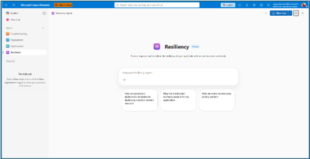
The distance between knowing and doing Most teams already know that zonal resiliency matters. What slows them down is everything in between: assessing posture across subscriptions and regions, deciding which gaps should be prioritized, writing the templates, and confirming the change actually rolled out. That is four separate workstreams, in four separate places, usually picked up long after the application is shipped. The resiliency agent closes that distance. We’re excited to announce that it is now available in public preview as part of the agents in Azure Copilot. The agent brings resiliency assessment, prioritized recommendations, and deployment-ready code into a single conversation, so resiliency becomes something your team does continuously rather than something you audit once a year. Learn more about Azure Copilot agents here. What the resiliency agent does The Resiliency agent is the conversational, action-oriented layer of Azure Infrastructure Resiliency Manager. The platform gives you a goal-driven view of your resiliency posture, and the agent lets you act on that posture in plain language. It brings together the signals you would otherwise chase manually across availability zones, Azure Backup, Azure Site Recovery, service level indicators, and Azure health models, then turns them into workload-aware guidance you can execute. Starting with zonal resiliency, it is designed to complement the resiliency capabilities you already rely on rather than replace them. The agent is built on the same foundational belief as Azure Infrastructure Resiliency Manager: application resiliency is a continuous journey, not a one-time task. That journey runs in three phases: Start Resilient Get Resilient Stay Resilient. This public preview addresses the activities associated with first two phases, frontloading the capabilities customers asked for most: direct remediation, Infrastructure as Code integration, and cost visibility. Stay Resilient comes next. What you can do in public preview Generate deployment-ready Bicep and Terraform with zone-redundant settings already enabled, before your first deployment Find the service groups and resources that are not zone resilient across your subscriptions and regions Prioritize remediation with cost-aware indicators that flag whether a fix needs extra spend, downtime, or redeployment Generate ready-to-deploy scripts to configure zone resiliency for supported resource types Create and update service groups so your applications are modeled correctly from the start Start resilient: build it in from the first line of code The most durable resiliency is the kind you never have to retrofit. Starting resilient means treating zone resiliency as an architectural requirement on day one, and the Resiliency Agent makes that the path of least resistance. Describe the application you are building, and the agent helps you generate deployment-ready Infrastructure as Code with the recommended resiliency configurations already enabled at creation time. Ask for a Bicep or Terraform template for a new workload and the agent returns one with zone-redundant settings pre-built for your databases, VMs, and load balancers, aligned to the goals you set. For example, try prompts like: “Generate a Bicep template for a zonally resilient VM setup.” “Create Terraform templates for a resilient architecture with VMs, AKS, and Storage.” The payoff: new services reach production already meeting your high availability standards, and the expensive redesign never has to happen. Get resilient: close the gaps in what you already run Applications change. The configuration that was right at first deployment is often not the one a business-critical workload needs two years later. This is where the resiliency agent turns posture insight into prioritized, executable action. Ask the agent to assess your environment, and it surfaces the resources and service groups that are not zone resilient, that are exposed to a datacenter outage, or that have key alerts waiting on attention. Every recommendation carries cost-aware decision support, qualitative indicators that flag whether a fix requires additional spend, downtime, or redeployment, so your team can sequence remediation against business value instead of guesswork. When you are ready to act, the agent generates ready-to-deploy scripts to configure zone resiliency for supported resource types, or targeted IaC snippets to close one specific gap. Try prompts like: “Assign resiliency goals for my application.” “Give me the posture of my service group: Contoso Payments.” “Enable zonal resiliency for my PostgreSQL server.” “Generate scripts to create a zonally resilient storage account.” This is a human-in-the-loop model by design. The agent brings the analysis, the recommendations, and the code. You keep full control over execution. Remediation gets faster without giving up governance. Stay resilient: what comes next Resiliency is not only about withstanding a zone outage. It is about protecting your data and knowing you can recover when something does go wrong. Recovery orchestration plans and zone drills are available today in Azure Infrastructure Resiliency Manager, and we are bringing both into the agent experience next. That closes the loop: assess, remediate, and validate recovery readiness in the same conversation. Get started with the public preview Open Azure Copilot and select the Resiliency Agent from the dropdown or the side panel. Three actions will get you value in the first session. Model your application. The agent works from your application, not a flat list of resources, so make sure it is represented as a service group that reflects your latest resource discovery. You can create service groups natively through the agent. Try: “Create a service group for my application.” Find your gaps. Ask which of your service groups and resources are not zone resilient. Most teams uncover exposure that was previously invisible. See Set resiliency goals and track compliance. Design it in. Ask for a Bicep template with zone-redundant defaults for a workload you plan to deploy and see how much retrofit effort disappears. See Generate resilient Bicep templates. What to expect in the preview Ready-to-deploy zone resiliency scripts are supported for Azure services that have zonal resiliency support in Infrastructure Resiliency Manager. See the support matrix for current coverage. Some advanced configurations, including multi-user authorization and Azure Site Recovery, may require manual steps, and the agent provides guidance to help you complete them. Where we are going This public preview is a starting line, not a finish. We are building toward end-to-end, agent-led journeys across Start, Get, and Stay Resilient, with cross-agent orchestration that reaches into migration, deployment, and observability, and multi-surface delivery so resiliency validation shows up in your IDEs, APIs, and CI/CD pipelines, not only in Azure Copilot. Service coverage will keep expanding, and the guidance will keep getting richer. The goal is simple and ambitious: make resilient-by-design the path of least resistance for every application on Azure. Preview is where that gets shaped, so tell us what is working and what you need next at azureresiliency@microsoft.com. Start here: open Azure Copilot, select the resiliency agent, and ask which of your applications are not zone resilient yet. Resources Announcing Azure Infrastructure Resiliency Manager public preview Agents in Azure Copilot public preview Resiliency capabilities in Agents (preview) in Azure Copilot, Azure Infrastructure Resiliency Manager overview Get started with service groups Microsoft Learn Questions or feedback: azureresiliency@microsoft.comSimpler, private connectivity between Azure and AWS with Azure Multicloud Interconnect
Multicloud is no longer the exception — it is how most enterprises operate. Teams run analytics in one cloud and applications in another, place workloads to meet data-residency requirements, and increasingly move large volumes of data between clouds to train and serve AI models. Yet the network that connects these environments has remained one of the hardest parts of a multicloud strategy to get right. Connecting Azure and AWS privately has traditionally meant stitching together Azure ExpressRoute, AWS Direct Connect, a connectivity provider or colocation footprint, customer-managed routers, BGP sessions, and link-layer encryption — then owning the resiliency design and day-to-day operations across all of it. The result is often slow to deliver, difficult to troubleshoot, and inconsistent in performance. Today, Microsoft and AWS are together introducing Azure Multicloud Interconnect, a jointly engineered, fully managed service that delivers private, high-throughput connectivity between Azure and AWS through a single logical resource. Both clouds coordinate provisioning, resiliency, encryption, and lifecycle operations, so the connection between your environments simply works — end to end. The challenge with connecting clouds today For most organizations, cross-cloud connectivity has been a build-it-yourself exercise. Establishing a private link between Azure and AWS typically requires provisioning an ExpressRoute circuit on one side and a Direct Connect circuit on the other, engaging a connectivity provider or securing space in a colocation facility to bridge them, and then configuring and maintaining the routers, BGP peering, and encryption that tie the two clouds together. Each of those pieces is owned by a different team or vendor, which makes the end-to-end path only as reliable as its least-managed component. When something breaks, isolating the root cause means coordinating across Microsoft, AWS, a network provider, and your own operations team — and mean time to resolution suffers as a result. Capacity planning is equally difficult: bandwidth is often provisioned for peak demand and left underused, while scaling up to meet a new AI or data initiative can take weeks. The outcome is a connectivity layer that is slow to stand up, expensive to operate, and hard to reason about — exactly the opposite of what a multicloud strategy is meant to deliver. Azure Multicloud Interconnect removes that complexity by turning cross-cloud connectivity into a managed service. What is Azure Multicloud Interconnect? Azure Multicloud Interconnect is a provider-managed, private intercloud connectivity service built on the proven foundations of Azure ExpressRoute and AWS Direct Connect. Instead of assembling and operating the underlying components yourself, you establish one interconnect resource and consume a private, dedicated path between your Azure and AWS environments. Under the covers, Microsoft and AWS coordinate the circuits, routing, and encryption on your behalf. You get the outcome you want — a reliable private connection between clouds — without becoming the systems integrator for it. Because the service builds on ExpressRoute and Direct Connect, it fits naturally into the connectivity models, tooling, and operational practices your teams already use in each cloud. One managed resource replaces a stack of circuits, routers, BGP sessions, and encryption you would otherwise build and operate yourself. Figure 1. Azure Multicloud Interconnect provides a single, managed private path between Azure and AWS, built on ExpressRoute and Direct Connect with a quad-redundant, 400G-class design and MACsec encryption. How it works Azure Multicloud Interconnect is engineered for the performance and availability that production and AI-scale workloads demand: A single logical connection. You provision and manage one interconnect resource. There are no customer-owned routers to rack, configure, or patch between the clouds. Quad-redundant, multi-site design. The data path is built across redundant devices and diverse sites — four Azure Microsoft Enterprise Edge (MSEE) routers and four AWS routers — so there is no single point of failure. High bandwidth backbone. A high-capacity LAG-based design provides the headroom needed for large-scale data movement and distributed AI traffic. Elastic bandwidth. Scale capacity up or down as demand changes, rather than provisioning for peak and paying for it year-round. Encryption by default. MACsec link-layer encryption is enabled automatically, so traffic between clouds is protected without extra configuration. Enterprise-ready networking. The service is IPv6-ready, supports APIPA addressing, and targets a 99.99% availability SLA. Routing and provisioning are coordinated by the platform, which removes the most common sources of cross-cloud connectivity errors — mismatched BGP configuration, inconsistent encryption settings, and asymmetric or fragile failover paths. A foundation you can trust Azure Multicloud Interconnect is not a new, unproven path — it extends two connectivity services that enterprises already rely on: Azure ExpressRoute and AWS Direct Connect. Both are private connectivity backbones trusted for mission-critical hybrid and cloud workloads, and the interconnect inherits their carrier-grade capacity, global edge presence, and operational maturity from day one. It also means your teams do not have to learn a separate model. The interconnect appears as a first-class resource governed by the identity, access, and monitoring controls each cloud already provides, and it can be automated with the tooling you use today. Extending trusted services, rather than introducing a parallel one, is what allows Microsoft and AWS to offer intercloud connectivity as a managed experience with confidence. Why this matters for your team Azure Multicloud Interconnect is designed to change the economics and the experience of running across clouds. Taken together, these benefits shift cross-cloud networking from a specialized, high-effort project to a repeatable, on-demand capability. Instead of dedicating senior engineers to build and babysit intercloud links, your team can direct that expertise toward the applications and data platforms that differentiate your business — while trusting that the connective tissue between clouds is reliable, secure, and ready to scale. Faster time to value. Turn up private Azure–AWS connectivity through a guided, managed workflow instead of a multi-week integration project spanning several vendors. Lower operational burden. Microsoft manages the infrastructure, resiliency, and lifecycle, so your networking team is freed from patching routers and diagnosing cross-cloud faults. Predictable, high performance. A dedicated, private path with high capacity that delivers the consistent throughput and low latency that public-internet or VPN paths cannot guarantee. Security you don’t have to assemble. Private connectivity plus default MACsec encryption keeps intercloud traffic off the public internet and protected in transit. A consistent experience in both clouds. Provision, monitor, and manage the interconnect using the native constructs and tooling your teams already rely on in Azure and AWS alike. Built for the way enterprises use multicloud “I've heard a very consistent message across many years of customer engagements - we are multi-cloud enterprise by design. With this announcement we are taking a burden on connecting clouds away from the customers." Igor Sakhnov, CVP Azure Networking Customers have told us where dedicated, managed intercloud connectivity makes the biggest difference. Azure Multicloud Interconnect is designed for scenarios such as: Distributed AI workloads. Move training data and model outputs between clouds at high throughput to feed pipelines wherever the compute lives. Large-scale data movement. Replicate datasets, back up across clouds, and support analytics that span Azure and AWS. Cross-cloud disaster recovery. Use a second cloud as a resilient recovery target over a private, reliable link. Hybrid and best-of-breed architectures. Run each application on the cloud that suits it best while keeping the connection between them private and performant. Regulated and sovereign workloads. Keep intercloud traffic on a private path to help meet data-residency and compliance requirements. Workload migration. Rehost or rebalance workloads between clouds without re-engineering connectivity for each move. Availability and what’s next Azure Multicloud Interconnect is launching first for Azure and AWS connectivity, the pairing customers ask about most often. Microsoft and AWS are starting with a preview so that you can validate the experience against your own architectures, with general availability to follow. This is the beginning of a broader journey. Building on existing multicloud connectivity capabilities, we plan to extend the managed interconnect model to additional clouds — including Google Cloud (coming soon)— so that a consistent, provider-managed experience can span your entire multicloud estate. As always, the roadmap will be guided by customer demand and real-world use. Our shared goal is simple: make the network the easiest part of your multicloud strategy, not the hardest. By delivering intercloud connectivity as a managed service, Microsoft and AWS want every organization — from a team moving its first dataset between clouds to an enterprise operating at AI scale — to connect Azure and AWS privately, securely, and with confidence, and to do it in minutes rather than months. Get started Learn more about Azure Multicloud Interconnect, Azure ExpressRoute, and AWS Direct Connect from Microsoft and AWS documentation, talk with your Microsoft or AWS account team about joining the preview, and tell us which cloud pairings and scenarios matter most for your organization. We are building this with your feedback. Azure Multicloud Interconnect is jointly delivered by Microsoft and AWS, built on Azure ExpressRoute and AWS Direct Connect. Feature availability, performance targets, and timelines may evolve as the service moves from preview to general availability.5.5KViews3likes0CommentsAzure Incident Retrospective - Please register! Session 2 - Tracking ID: ZJV6-SGG-BW8
Join our upcoming live webcast for a transparent discussion about this recent Azure service incident led by our engineering teams. Network connectivity issues in West US Tracking ID: ZJV6-SGG | Impacted: 23 July 2026 Same content presented in both sessions: pick the one that works best for your timezone! What to expect 📚 Understand What happened, how we responded, and what we learned 💬 Ask Live Q&A with our engineering experts throughout the session 🛠 Learn The fixes we've put in place and guidance for workload resiliency Choose your session Same content presented at both times: pick the one that works best for your timezone: Session 1 17:30 UTC Thursday, 27 Aug 2026 Register now → Session 2 05:30 UTC Friday, 28 Aug 2026 Register now → 10:30 AM US Pacific (PDT) 1:30 PM US Eastern (EDT) 6:30 PM London (BST) 1:30 AM +1 Beijing (CST) 3:30 AM +1 Sydney (AEDT) 5:30 AM +1 Auckland (NZDT) 10:30 PM -1 US Pacific (PDT) 1:30 AM US Eastern (EDT) 6:30 AM London (BST) 1:30 PM Beijing (CST) 3:30 PM Sydney (AEDT) 5:30 PM Auckland (NZDT) Our engineering leaders Jamie Gaudette Vice President Azure Networking Cloud+AI Engineering LinkedIn ↗ ⚠️ Prepare before the livestream Read the Post Incident Review (PIR) ahead of time so you can ask any follow up questions during the live Q&A Helpful resources 🔔 Azure Service Health Alerts Get alerts for relevant incidents by setting up notifications via email, SMS, or webhook 🎥 Past Retrospective Recordings Watch recordings of previous retrospective livestreams 📄 Azure Post Incident Reviews Learn more about PIRs and the retrospective program216Views0likes0CommentsAzure Incident Retrospective - Please register! Session 1 - Tracking ID: ZJV6-SGG-BW8
Join our upcoming live webcast for a transparent discussion about this recent Azure service incident led by our engineering teams. Network connectivity issues in West US Tracking ID: ZJV6-SGG | Impacted: 23 July 2026 Same content presented in both sessions: pick the one that works best for your timezone! What to expect 📚 Understand What happened, how we responded, and what we learned 💬 Ask Live Q&A with our engineering experts throughout the session 🛠 Learn The fixes we've put in place and guidance for workload resiliency Choose your session Same content presented at both times: pick the one that works best for your timezone: Session 1 17:30 UTC Thursday, 27 Aug 2026 Register now → Session 2 05:30 UTC Friday, 28 Aug 2026 Register now → 10:30 AM US Pacific (PDT) 1:30 PM US Eastern (EDT) 6:30 PM London (BST) 1:30 AM +1 Beijing (CST) 3:30 AM +1 Sydney (AEDT) 5:30 AM +1 Auckland (NZDT) 10:30 PM -1 US Pacific (PDT) 1:30 AM US Eastern (EDT) 6:30 AM London (BST) 1:30 PM Beijing (CST) 3:30 PM Sydney (AEDT) 5:30 PM Auckland (NZDT) Our engineering leaders Jamie Gaudette Vice President Azure Networking Cloud+AI Engineering LinkedIn ↗ ⚠️ Prepare before the livestream Read the Post Incident Review (PIR) ahead of time so you can ask any follow up questions during the live Q&A Helpful resources 🔔 Azure Service Health Alerts Get alerts for relevant incidents by setting up notifications via email, SMS, or webhook 🎥 Past Retrospective Recordings Watch recordings of previous retrospective livestreams 📄 Azure Post Incident Reviews Learn more about PIRs and the retrospective program215Views1like0Comments