virtual network
254 Topics
Azure Networking: Request for Granular Control of “Allow Azure Services and Resources”
I would like to get the Azure community’s thoughts on a networking/security improvement that I believe could help organizations implement a stronger least-privilege model. Several Azure resources provide an option similar to: “Allow Azure services and resources to access this resource.” This is useful when an Azure service needs to access another Azure resource, but the current option can be quite broad. Example: Power BI → Azure SQL For example, suppose Power BI Service needs to access an Azure SQL Server. The actual requirement might be: Power BI → Specific Azure SQL Server = Allow However, the available option may require enabling: “Allow Azure services and resources to access this server” This effectively creates a much broader trusted-service exception than the actual requirement. Ideally, I would like to see something like: Azure SQL Server │ ├── Power BI Service → Allow ├── Azure Data Factory → Deny ├── Azure Functions → Deny ├── Azure App Service → Deny └── Other Azure Services → Deny Proposed improvement Could Microsoft provide an additional option such as: “Allow selected Azure services and resources” where customers can explicitly select which Azure service/resource is allowed to bypass the network restriction? Depending on the Azure service, the selection could potentially be based on: Specific Azure service Specific Azure resource Resource ID Subscription Resource group Tenant Managed identity / Entra identity Specific service instance For example: Trusted Azure Services / Resources Power BI → Production Analytics → Allow All other Azure services → Deny Why I think this would be useful This would give customers a middle ground between: Disabling public access and implementing Private Endpoint/private connectivity, or Allowing all Azure services/resources through the broad trusted-service exception. A granular trusted-service model would allow: Only the Azure service/resource that actually requires access is trusted. This would better support least privilege, Zero Trust, security, and compliance requirements. Broader Azure applicability My suggestion is not specifically for Azure SQL. The Power BI → Azure SQL scenario is just an example. I think this could be a common Azure networking capability for all Azure resources that currently support a trusted Azure services / “Allow Azure services and resources” type of bypass. I would be interested to hear from the Azure community and Microsoft: Is there already a way to achieve this level of granularity? Are there architectural/security reasons why this cannot currently be implemented? Is Microsoft considering a more granular trusted-service model? Would a feature like “Allow selected Azure services/resources” be technically feasible? I would appreciate any feedback or guidance from the Azure networking/service teams.361Views0likes1Comment
Azure VM Losing Network Connectivity after Doomain Removal
I currently have Azure VM domain joined servers running Server 2019 Std which are being upgraded via an in-place upgrade to Server 2025 Std. After the upgrade I will be un-joining from the domain and then joining a WORKGROUP to allow Entra ID joining of the servers. I have completed this on a non-critical server but upon removing from the domain the server appears to have lost network connectivity and displays a Computer Icon with a flashing cable, then eventually fails. I noticed the Ethernet displays now “Public” so I changed back to “Private” and removed “Network Level Authentication” from RDP. I also removed the Custom DNS server settings that were on the NIC in Azure Portal and set to “Virtual Network Inherited” to allow Azure DNS. Unfortunately, the same events occur time and time again with no network connectivity. I have reset the NIC and network via Powershell and CMD commands as suggested in most Google searches along with recreating the VM NIC in Azure, but still the same! Does anyone have any idea what could be causing the issue and how to resolve it as someone must have experienced similar in the past when unjoining an Azure VM from a corporate domain? I have been directing all traffic from server via the Azure FW using a Route table with a route directing all traffic via Azure FW and associating the subnets being used: Address Prefix: 0.0.0.0/0 - Next Hop type: Virtual Appliance – Next Hop IP address: <IP of Azure FW Private IP> I assume this would remain the same too? Please any advice or suggestions would be greatly appreciated? Thanks267Views0likes2CommentsAdvertised gateway prefixes in Azure
Introduction Large Azure hub-and-spoke environments can advertise a significant number of routes toward on-premises networks. By default, Azure VPN Gateway and ExpressRoute Gateway advertise the address spaces of the hub virtual network and the address spaces of peered spoke virtual networks that use gateway transit. As the number of spokes and address spaces grows, the border gateway protocol (BGP) route table grows as well. Advertised gateway prefixes provide a native way to summarize those Azure-side routes. The feature is configured on the hub virtual network through the summarizedGatewayPrefixes property, which is exposed in the Azure portal as Advertised gateway prefixes. Fewer BGP prefixes Replace many individual networks with one or more aggregated CIDRs. Better scale management Help large hub-and-spoke designs stay within advertised-prefix limits. Cleaner route visibility Make the intended Azure address plan easier to recognize on provider and on-premises route views. In this blog we will demonstrate leveraging Advertised gateway prefixes to summarize many Azure advertised prefixes into one. What are advertised gateway prefixes? Advertised gateway prefixes are summarized CIDR blocks that an Azure hybrid gateway advertises toward on-premises instead of advertising every covered hub and spoke address space individually. The configuration belongs on the gateway virtual network, usually the hub VNet that contains GatewaySubnet and the ExpressRoute or VPN gateway. How the route advertisement changes Default behavior With advertised gateway prefixes Hub: 10.27.0.0/24 Spoke 1: 10.27.1.0/24 Spoke 2: 10.27.2.0/24 Spoke 3: 10.27.3.0/24 Summary: 10.27.0.0/22 Four individual prefixes are advertised. One summary prefix is advertised. A spoke outside the summary is still advertised separately. Example: 172.16.1.0/24 remains visible if it is not covered by 10.27.0.0/22. When should you use it? You use a hub-and-spoke topology with gateway transit and many spoke address spaces. You want to advertise a covering prefix, such as a /16, instead of many smaller prefixes, such as multiple /24 networks. You are approaching ExpressRoute advertised-prefix limits or want to reduce route-table growth before scale becomes a problem. Your Azure address plan is sufficiently structured to create safe, intentional summary ranges. Note: ExpressRoute scale context: Microsoft documentation lists a maximum of 1,000 IPv4 prefixes and 100 IPv6 prefixes advertised from a virtual network to on-premises on a single ExpressRoute connection through private peering. Exceeding the connection prefix limit can cause the connection between the circuit and gateway to disconnect until the prefix count is reduced. Prerequisites A hub virtual network with GatewaySubnet. An ExpressRoute gateway or VPN gateway deployed in the hub virtual network. One or more peered spoke virtual networks if you want to demonstrate route summarization across spokes. A planned IPv4 and, when applicable, IPv6 summary that covers the intended hub and spoke address spaces. Access to the provider or on-premises BGP route view for validation. In this walkthrough, Megaport is used as the external verification point. Configure advertised gateway prefixes in the Azure portal The portal configuration is performed on the hub VNet, not on the ExpressRoute circuit and not on each spoke VNet. In the Azure portal, search for Virtual networks and select the hub VNet that contains GatewaySubnet. Open the hub virtual network Under Settings, select Address space. Open Address space In Advertised gateway prefixes, select + Add prefix. Enter the covering CIDR, such as 10.0.0.0/22 for four contiguous /24 networks. Add the summarized prefix For a dual-stack design, add IPv4 and IPv6 summarized prefixes explicitly. Add additional address families if needed Select Save and confirm the summarized prefixes remain listed in the Advertised gateway prefixes section. Save the configuration Validate the summarized route on routers or provider After Azure applies the change and BGP converges, I’m using ExpressRoute and Megaport here for my example, you can either log in to your router directly or view the incoming BGP routes via your provider’s interface to confirm what routes are being received from Azure. We want to capture a view that displays the BGP prefixes learned from the Azure side. Capture a baseline screenshot before enabling the feature, showing the individual hub and spoke prefixes. After configuration, refresh the route view and locate the new summarized prefix. Confirm that covered hub and spoke prefixes are no longer advertised individually. Confirm that any address space outside the configured summary remains advertised separately. Before: After: In my demo environment I have a hub and 20 spokes all within the 10.27.0.0/16 address prefix. We can see a successful implementation as before enabling the feature, I had a total of 21 prefixes being received at Megaport, after enabling the feature I have 1. Important design considerations Configure the hub, not the spokes: Only the virtual network containing the gateway subnet uses the summarizedGatewayPrefixes property for this behavior. A value placed on a spoke VNet is ignored. Avoid overlap within the prefix list: Do not configure overlapping entries in the advertised gateway prefixes list. Expect uncovered networks to remain visible: If a hub or spoke address space is not covered by a configured summary, the gateway continues to advertise it individually. Plan dual-stack explicitly: IPv4 and IPv6 summaries must be added separately. Removing all entries restores default behavior: When every advertised gateway prefix is removed, Azure returns to advertising hub and peered spoke address spaces individually. Protect the on-premises edge: Use appropriate route policies so only expected prefixes are accepted. Summarization simplifies advertisements, but it does not replace routing governance. Conclusion Advertised gateway prefixes give Azure networking teams a straightforward, native method to control route scale from a gateway-enabled hub VNet. Instead of sending every hub and spoke prefix across ExpressRoute or VPN connections, the gateway can advertise a concise list of summarized prefixes. The result is a smaller and more intentional route advertisement, while uncovered address spaces remain visible for compatibility. References Advertised gateway prefixes in Azure virtual networks Configure advertised gateway prefixes using the Azure portal Azure ExpressRoute FAQ About ExpressRoute virtual network gateways649Views0likes0CommentsInter-Hub Connectivity Using Azure Route Server
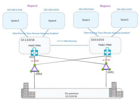
By Mays_Algebary shruthi_nair As your Azure footprint grows with a hub-and-spoke topology, managing User-Defined Routes (UDRs) for inter-hub connectivity can quickly become complex and error-prone. In this article, we’ll explore how Azure Route Server (ARS) can help streamline inter-hub routing by dynamically learning and advertising routes between hubs, reducing manual overhead and improving scalability. Baseline Architecture The baseline architecture includes two Hub VNets, each peered with their respective local spoke VNets as well as with the other Hub VNet for inter-hub connectivity. Both hubs are connected to local and remote ExpressRoute circuits in a bowtie configuration to ensure high availability and redundancy, with Weight used to prefer the local ExpressRoute circuit over the remote one. To maintain predictable routing behavior, the VNet-to-VNet configuration on the ExpressRoute Gateway should be disabled. Note: Adding ARS to an existing Hub with Virtual Network Gateway will cause downtime that expect to last 10 minutes. Scenario 1: ARS and NVA Coexist in the Hub Option A: Full Traffic Inspection ARS and NVA Coexist in the Hub In this scenario, ARS is deployed in each Hub VNet, alongside the Network Virtual Appliances (NVAs). NVA1 in Region1 establishes BGP peering with both the local ARS (ARS1) and the remote ARS (ARS2). Similarly, NVA2 in Region2 peers with both ARS2 (local) and ARS1 (remote). Let’s break down what each BGP peering relationship accomplishes. For clarity, we’ll focus on Region1, though the same logic applies to Region2: NVA1 Peering with Local ARS1 Through BGP peering with ARS1, NVA1 dynamically learns the prefixes of Spoke1 and Spoke2 at the OS level, eliminating the need to manually configure these routes. The same applies for NVA2 learning Spoke3 and Spoke4 prefixes via its BGP peering with ARS2. NVA1 Peering with Remote ARS2 When NVA1 peers with ARS2, the Spoke1 and Spoke2 prefixes are propagated to ARS2. ARS2 then injects these prefixes into NVA2 at both the NIC level with NVA1 as the next hop, and at the OS level. This mechanism removes the need for UDRs on the NVA subnets to enable inter-hub routing. Additionally, ARS2 advertises the Spoke1 and Spoke2 prefixes to both ExpressRoute circuits (EXR2 and EXR1 due to bowtie configuration) via GW2. 👉Important: To ensure that ARS2 accepts and propagates Spoke1/Spoke2 prefixes received via NVA1, AS-Override must be enabled. Without AS-Override, BGP loop prevention will block these routes at ARS2, since both ARS1 and ARS2 use the default ASN 65515, and ARS2 will consider the route as already originated locally. The same principle applies in reverse for Spoke3 and Spoke4 prefixes being advertised from NVA2 to ARS1. Traffic Flow Inter-Hub Traffic: Spoke VNets are configured with UDRs that contain only a default route (0.0.0.0/0) pointing to the local NVA as the next hop. Additionally, the “Propagate Gateway Routes” setting should be set to False to ensure all traffic, whether East-West (intra-hub/inter-hub) or North-South (to/from internet), is forced through the local NVA for inspection. Local NVAs will have the next hop to the other region spokes injected at the NIC level by local ARS, pointing to the other region NVA, for example NVA2 will have next hop to Spoke1 and Spoke2 as NVA1 (10.0.1.4) and vice versa. Why are UDRs still needed on spokes if ARS handles dynamic routing? Even with ARS in place, UDRs are required to maintain control of the next hop for traffic inspection. For instance, if Spoke1 and Spoke2 do not have UDRs, they will learn the remote spoke prefixes (e.g., Spoke3/Spoke4) injected via ARS1, which received them from NVA2. This results in Spoke1/Spoke2 attempting to route traffic directly to NVA2, a path that is invalid, since the spokes don’t have the path to NVA2. The UDR ensures traffic correctly routes through NVA1 instead. On-Premises Traffic: To explain the on-premises traffic flow, we'll break it down into two directions: Azure to on-premises, and on-premises to Azure. Azure to On-Premises Traffic Flow: As previously noted, Spokes send all traffic, including traffic to on-premises, via NVA1 due to the default route in the UDR. NVA1 then routes traffic to the local ExpressRoute circuit, using Weight to prefer the local path over the remote. Note: While NVA1 learns on-premises prefixes from both local and remote ARSs at the OS level, this doesn’t affect routing decisions. The actual NIC-level route injection determines the next hop, ensuring traffic is sent via the correct path—even if the OS selects a different “best” route internally. The screenshot below from NVA1 shows four next hops to the on-premises network 10.2.0.0/16. These include the local ARS (ARS1: 10.0.2.5 and 10.0.2.4) and the remote ARS (ARS2: 10.1.2.5 and 10.1.2.4). On-Premises to Azure Traffic Flow In a bowtie ExpressRoute configuration, Azure VNet prefixes are advertised to on-premises through both local and remote ExpressRoute circuits. Because of this dual advertisement, the on-premises network must ensure optimal path selection when routing traffic to Azure. From Azure side, to maintain traffic symmetry, add UDRs at the GatewaySubnet (GW1 and GW2) with specific routes to the local Spoke VNets, using the local NVA as the next hop. This ensures return traffic flows back through the same path it entered. 👉How Does the ExpressRoute Edge Router Select the Optimal Path? You might ask: If Spoke prefixes are advertised by both GW1 and GW2, how does the ExpressRoute edge router choose the best path? (e.g., diagram below shows EXR1 learns Region1 prefixes from GW1 and GW2) Here’s how: Edge routers (like EXR1) receive the same Spoke prefixes from both gateways. However, these routes have different AS-Path lengths: - Routes from the local gateway (GW1) have a shorter AS-Path. - Routes from the remote gateway (GW2) have a longer AS-Path because NVA1’s ASN (e.g., 65001) is prepended twice as part of the AS-Override mechanism. As a result, the edge router (EXR1) will prefer the local path from GW1, ensuring efficient and predictable routing. For example: EXR1 receives Spoke1, Spoke2, and Hub1-VNet prefixes from both GW1 and GW2. But because the path via GW1 has a shorter AS-Path, EXR1 will select that as the best route. (Refer to the diagram below for a visual of the AS-Path difference). Final Traffic Flow: Option-A Insights: This design simplifies UDR configuration for inter-hub routing, especially useful when dealing with non-contiguous prefixes or operating across multiple hubs. For simplicity, we used a single NVA in each Hub-VNet while explaining the setup and traffic flow throughout this article. However, a high available (HA) NVA deployment is recommended. To maintain traffic symmetry in an HA setup, you’ll need to enable the next-hop IP feature when peering with Azure Route Server (ARS). When on-premises traffic inspection is required, the UDR setup in the GatewaySubnet becomes more complex as the number of Spokes increases. As your Azure network scales, keep in mind that Azure Route Server supports a maximum of 16 BGP peers per instance (as of the time writing this article). This limit can impact architectures involving multiple NVAs or hubs. Option B: Bypass On-Premises Inspection If on-premises traffic inspection is not required, NVAs can advertise a supernet prefix summarizing the local Spoke VNets to the remote ARS. This approach provides granular control over which traffic is routed through the NVA and eliminates the need for BGP peering between the local NVA and local ARS. All other aspects of the architecture remain the same as described in Option A. For example, NVA2 can advertise the supernet 192.168.2.0/23 (supernet of Spoke3 and Spoke4) to ARS1. As a result, Spoke1 and Spoke2 will learn this route with NVA2 as the next hop. To ensure proper routing (as discussed earlier) and inter-hub inspection, you need apply a UDR in Spoke1 and Spoke2 that overrides this exact supernet prefix, redirecting traffic to NVA1 as the next hop. At the same time, traffic destined for on-premises will follow the system route through the local ExpressRoute gateway, bypassing NVA1 altogether. In this setup: UDRs on the Spokes should have "Propagate Gateway Routes" set to True. No UDRs are needed in the GatewaySubnet. 👉Can NVA2 Still Advertise Specific Spoke Prefixes? You might wonder: Can NVA2 still advertise specific prefixes (e.g., Spoke3 and Spoke4) learned from ARS2 to ARS1 instead of a supernet? Yes, this is technically possible, but it requires maintaining BGP peering between NVA2 and ARS2. However, this introduces UDR complexity in Spoke1 and Spoke2, as you'd need to manually override each specific prefix. This also defeats the purpose of using ARS for simplified route propagation, undermining the efficiency and scalability of the design. Bypass On-Premises Inspection Final Traffic Flow: Option B: Bypass on-premises inspection traffic flow Option-B Insights: This approach reduces the number of BGP peerings per ARS. Instead of maintaining two BGP sessions (local NVA and remote NVA) per Hub, you can limit it to just one, preserving capacity within ARS’s 8-peer limit for additional inter-hub NVA peerings. Each NVA should advertise a supernet prefix to the remote ARS. This can be challenging if your Spokes don’t use contiguous IP address spaces, as described in Option B. Scenario 2: ARS in the Hub and the NVA in Transit VNet In Scenario 1, we highlighted that when on-premises inspection is required, managing UDRs at the GatewaySubnet becomes increasingly complex as the number of Spoke VNets grows. This is due to the need for UDRs to include specific prefixes for each Spoke VNet. In this scenario, we eliminate the need to apply UDRs at the GatewaySubnet altogether. A in Transit VNet In this design, the NVA will be deployed in Transit VNet, where: Transit-VNet will be peered with local Spoke VNets and with the local Hub-VNet to enable intra-Hub and on-premises connectivity. Transit-VNet also peered with remote Transit VNets (e.g., Transit-VNet1 peered with Transit-VNet2) to handle inter-Hub connectivity through the NVAs. Additionally, Transit-VNets are peered with remote Hub-VNets, to establish BGP peering with the remote ARS. NVAs OS will need to add static routes for the local Spoke VNets prefixes, it can be specific or it can supernet prefix, which will later be advertised to ARSs over BGP Peering, then ARS will advertise it to on-premises via ExpressRoute. NVAs will BGP peer with local ARS and also with the remote ARS. To understand the reasoning behind this design, let’s take a closer look at the setup in Region1, focusing on how ARS and NVA are configured to connect to Region2. This will help illustrate both inter-hub and on-premises connectivity. The same concept applies in reverse from Region2 to Region1. Inetr-Hub: To enable NVA1 in Region1 to learn prefixes from Region2, NVA2 will configure static routes at the OS level for Spoke3 and Spoke4 (or their supernet prefix) and advertise them to ARS1 via remote BGP peering. As a result, these prefixes will be received by NVA1, both at the NIC level, with NVA2 as the next hop, and at the OS level for proper routing. Spoke1 and Spoke2 will have a UDR with a default route pointing to NVA1 as the next hop. For instance, when Spoke1 needs to communicate with Spoke3, the traffic will first route through NVA1. NVA1 will then forward the traffic to NVA2 using VNet peering between the two Hubs. A similar configuration will be applied in Region2, where NVA1 will configure static routes at the OS level for Spoke1 and Spoke2 (or their supernet prefix) and advertise them to ARS2 via remote BGP peering, as a result, these prefixes will be received by NVA2, both at the NIC level (injected by ARS2), with NVA1 as the next hop, and at the OS level for proper routing. Note: At the OS level, NVA1 learns Spoke3 and Spoke4 prefixes from both local and remote ARSs. However, the NIC-level route injection determines the actual next hop, so even if the OS selects a different best route, it won’t affect forwarding behavior. same applies to NVA2. On-Premises Traffic: To explain the on-premises traffic flow, we'll break it down into two directions: Azure to on-premises, and on-premises to Azure. Azure to On-Premises Traffic Flow: Spokes in Region1 route all traffic through NVA1 via a default route defined in their UDRs. Because of BGP peering between NVA1 and ARS1, ARS1 advertises the Spoke1 and Spoke2 (or their supernet prefix) to on-premises through ExpressRoute (EXR1). The Transit-VNet1 (hosting NVA1) is peered with Hub1-VNet, with “Use Remote Gateway” enabled. This allows NVA1 to learn on-premises prefixes from the local ExpressRoute gateway (GW1), and traffic to on-premises is routed through the local ExpressRoute circuit (EXR1) due to higher BGP Weight configuration. Note: At the OS level, NVA1 learns on-prem prefixes from both local and remote ARSs. However, the NIC-level route injection determines the actual next hop, so even if the OS selects a different best route, it won’t affect forwarding behavior. same applies to NVA2. On-Premises to Azure Traffic Flow: Through BGP peering with ARS1, NVA1 enables ARS1 to advertise Spoke1 and Spoke2 (or their supernet prefix) to both EXR1 and EXR2 circuits (due to the ExpressRoute bowtie setup). Additionally, due to BGP peering between NVA1 and ARS2, ARS2 also advertises Spoke1 and Spoke2 (or their supernet prefix) to EXR2 and EXR1 circuits. As a result, both ExpressRoute edge routers in Region1 and Region2 learn the same Spoke prefixes (or their supernet prefix) from both GW1 and GW2, with identical AS-Path lengths, as shown below. EXR1 learns Region1 Spokes's supernet prefixes from GW1 and GW2 This causes non-optimal inbound routing, where traffic from on-premises destined to Region1 Spokes may first land in Region2’s Hub2-VNet before traversing to NVA1 in Region1. However, return traffic from Spoke1 and Spoke2 will always exit through Hub1-VNet. To prevent suboptimal routing, configure NVA1 to prepend the AS path for Spoke1 and Spoke2 (or their supernet prefix) when advertising them to the remote ARS2. Likewise, ensure NVA2 prepends the AS path for Spoke3 and Spoke4 (or their supernet prefix) when advertising to ARS1. This approach helps maintain optimal routing under normal conditions and during ExpressRoute failover scenarios. Below diagram shows NVA1 is setting AS-Prepend for Spoke1 and Spoke2 supernet prefix when BGP peer with remote ARS (ARS1), same will apply for NVA2 when advertising Spoke3 and Spoke4 prefixes to ARS1. Final Traffic Flow: Full Inspection: Traffic flow when NVA in Transit-VNet Insights: This solution is ideal when full traffic inspection is required. Unlike Scenario 1 - Option A, it eliminates the need for UDRs in the GatewaySubnet. When ARS is deployed in a VNet (typically in Hub VNets), the VNet will be limited to 500 VNet peerings (as of the time writing this article). However, in this design, Spokes peer with the Transit-VNet instead of directly with the ARS VNet, allowing you to scale beyond the 500-peer limit by leveraging Azure Virtual Network Manager (AVNM) or submitting a support request. Some enterprise customers may encounter the 1,000-route advertisement limit on the ExpressRoute circuit from the ExpressRoute gateway. With Summarized Gateway Prefixes now generally available, Azure provides native control to summarize VNet address spaces before advertising them to ExpressRoute. This helps reduce the advertised route count without relying solely on NVAs for summarization. For simplicity, we used a single NVA in each Hub-VNet while explaining the setup and traffic flow throughout this article. However, a high available (HA) NVA deployment is recommended. To maintain traffic symmetry in an HA setup, you’ll need to enable the next-hop IP feature when peering with Azure Route Server (ARS). This design does require additional VNet peerings, including: Between Transit-VNets (inter-region), Between Transit-VNets and local Spokes, and Between Transit-VNets and both local and remote Hub-VNets.3.8KViews5likes2Comments
Announcing Public Preview - Azure Private Link over IPv6
1. Overview Private Link over IPv6 (PL IPv6) enables customers to securely access Azure PaaS services over IPv6-based connectivity. This capability is critical for: IPv6 based PE connectivity to PaaS resources Enabling IPv6 in On-prem environments This document is intended to serve as guide to setup and test the On-prem connectivity from IPv6 customer address to Azure PaaS resources over Express Route via Private link. (IPv6 PE connectivity) Note: This feature is currently in public preview and is not recommended for production workloads. 2. Supported Scenarios Scenario A: Native Azure (Azure VM → PaaS via IPv6 Private Endpoint) IPv6 client VM in VNet → IPv6 Private Endpoint → Azure PaaS Scenario B: OnPrem Access via ExpressRoute On-prem IPv6 client → ExpressRoute → VNet Routing Appliance (VNRA) à IPv6 Private Endpoint → PaaS Supported via ER Circuits 3. Prerequisites 3.1 Supported Regions (Preview Scope) Limited preview regions West Central US East Asia UK South US Central North Europe 3.2 Supported Services (Preview) Azure Storage Azure SQL Azure Key Vault Azure Data Explorer 3.3. Subscription registration An Azure account with an active subscription. Create an account for free. Your subscription must be registered for the Private Link over IPv6 preview. Registration is mandatory before you configure any resources. You can self-register the subscription by running the following commands: az feature register --namespace Microsoft.Network --name SupportIPv6PrivateEndpoint --subscription <subscription-id> az provider register --namespace Microsoft.Network 4. Configurations 4.1 Azure VNET level configurations Please note that you will need to create: Dual-stack IPv6-enabled Vnet with a VM that is assigned both IPv4 and IPv6 address. For on-prem connectivity, this is the same Vnet where ER Gateway is created. Refer: Create an Azure virtual machine with a dual-stack network - Azure Virtual Network | Microsoft Learn PL scale enabled on VNET via configuration flags (refer config flags mentioned further in this section and bolded flags in the code snippet) Dual Stack (IPv4+ IPv6) Subnet Private Endpoints with IPv6 Refer these flags for enabling VNET with PL scale: Vnet level : "privateEndpointVNetPolicies": "Basic", Subnet level: “privateEndpointNetworkPolicies": "RouteTableEnabled" Refer Azure documentation for VNET creation: Quickstart: Create an Azure Virtual Network | Microsoft Learn 4.3 Private endpoint configuration: With the Private Link IPv6 support, we have introduced a new parameter in PE creation API/CLI, ‘ip VersionType’. Please ensure that this is set to ‘IPv6’ for enabling PL IPv6 traffic. Refer Azure documentation for PE creation: Quickstart: Create a private endpoint - Azure portal - Azure Private Link | Microsoft Learn Reference CLI: az network private-endpoint create \ --name <private-endpoint-name> \ --resource-group <resource-group-name> \ --vnet-name <vnet-name> \ --subnet <subnet-name> \ --private-connection-resource-id <resource-id-of-target-service> \ --group-id <group-id> \ --connection-name <connection-name> \ --location <region> \ --ip-version-type <Ipv4|Ipv6 > 4.4 DNS Configuration Ensure these points for DNS configurations: Create Private DNS Zone for each Service type Attach the respective DNS zone to the Private Endpoints. Ensure to check that after above steps completed PaaS FQDN resolves to PEIPv6 address. Refer Azure documentation for On-prem access via Private Link: Azure Private Endpoint DNS Integration Scenarios | Microsoft Learn Native Azure Connectivity (Azure VM → PaaS via IPv6) Validation: Ensure the Storage Account FQDN resolves to the IPv6 Private Endpoint address. Access the Storage Account using the standard service FQDN. From the dual-stack VM: nslookup <storageaccount>.blob.core.windows.net Expected Result: <storageaccount>.privatelink.blob.core.windows.net AAAA: <Private Endpoint IPv6 Address> Connectivity validation: curl https://<storageaccount>.blob.core.windows.net Test-NetConnection <storageaccount>.blob.core.windows.net -Port 443 Configurations specific to On-prem connectivity via ER circuit and Virtual Network Routing Appliance On-premises IPv6 clients access IPv6 private endpoints over ExpressRoute through a Virtual Network Routing Appliance (VNRA). ExpressRoute forwards traffic from on-premises IPv6 clients to the VNRA, which then routes the traffic to the target IPv6 private endpoint that's hosted by the Azure PaaS service. This connectivity requires the following components: An ExpressRoute circuit with the appropriate gateway SKU for your connectivity type (FastPath or standard). For more information, see Create and modify an ExpressRoute circuit. 4.5 Virtual Network Routing Appliance (VNRA) configurations To know more about VNRA, refer: Overview of Routing Appliances - Azure Virtual Network | Microsoft Learn We are leveraging VNRA to facilitate PL IPv6 ER traffic forwarding. User would be required to create a VNRA in the VNet. To facilitate the forwarding of PL IPv6 traffic via VNRA, a UDR would be required to be added in the gateway subnet with next hop as VNRA IPv6 address. Below are the guided steps to achieve all of this. Step 1: Create a VNRA in the VNet Create a VNRA in your resource group via Azure Preview portal. Search for Azure Virtual Network routing appliance on the Azure portal search Click on create: In the above creation page, choose your subscription and resource group, enter name, region, capacity (10-200 Gbps) & the VNet. Review and Create the VNRA. Step 2: Create User Defined Route (UDR) to VNRA The UDR will ensure ER PLIPv6 traffic is forwarded to VNRA which will further process & forward the traffic to the IPv6 Private Endpoint. 1.Create a new route table on Azure portal: 2. Choose the subscription, resource group and set ‘Gateway propagation’ as default (true) 3. Add a route in this route table to forward the on-prem PLIPv6 traffic to VNRA (for this please add route as shown in reference below) as per below details: Enter ‘Destination type’ as ‘IP Address’ Enter ‘Destination IP addresses/CIDR Ranges’ as Private Endpoint IPv6 subnet range - This is the subnet on which your Private Endpoint resides to which the traffic would be sent Enter ‘Next hop’ as “Virtual Appliance”, Give the ‘Next hop address’ as the IPv6 address of VNRA 4.Attach this route table to the Gateway subnet This completes the VNRA setup. 5. Validate Connectivity After establishing configuration and deploying your setup, you can run following validations: From OnPrem VM: Perform DNS lookup on PaaS FQDN → confirm IPv6 PE resolution Connect using PaaS FQDN Validation Checks VM → PE connectivity over IPv6 Data plane traffic successful 6. Preview Considerations Limited regional availability (Check preview regions above) Destination PaaS resource must be in the same region as the Private Endppint. Cross region connectivity is not supported in this release. Limited PaaS onboarding (Azure Storage, Azure SQL, Azure Key Vault, Azure Data Explorer) Current on-premises connectivity support is limited to ExpressRoute-based scenarios and does not currently include VPN, Virtual WAN (vWAN), or Network Virtual Appliances (NVAs). In Private Link IPv6 scenarios, the original client IPv6 address is not preserved in downstream service logs. Due to implicit NAT translation, logs will display the VNet-side translated source IP address instead. Link to Azure documentation: Configure Azure Private Link over IPv6 (Preview) - Azure Private Link | Microsoft Learn541Views0likes0CommentsAzure Virtual Network routing appliance is now generally available
Modern cloud networks are evolving faster than ever. Organizations are building larger AI platforms, connecting more services through private connectivity, adopting IPv6, and expanding applications across regions and business units. As these environments grow, the network becomes a critical foundation for delivering performance, resiliency, and operational simplicity. Today, we're excited to announce the general availability of Azure Virtual Network routing appliance, a managed, platform-native routing service designed to provide high-performance connectivity across Azure virtual networks at cloud scale. Virtual Network routing appliance brings together Azure-native operations, specialized networking infrastructure, built-in resiliency, and high-bandwidth forwarding to help organizations build the next generation of cloud network architectures. Built for the era of AI infrastructure AI is changing the scale at which networks operate. Training clusters, inference services, analytics platforms, data processing pipelines, and distributed application environments generate unprecedented volumes of east-west traffic. These workloads require high-performance connectivity between services, networks, and regions while maintaining operational simplicity. Virtual Network routing appliance provides a managed routing foundation for these environments, enabling organizations to scale network connectivity alongside their AI investments. Instead of building and operating custom routing infrastructure, teams can focus on accelerating innovation, deploying new services, and delivering business outcomes. Scale hub-and-spoke architectures Hub-and-spoke remains one of the most widely adopted network architectures in Azure because it provides centralized governance, simplified operations, and efficient connectivity. As organizations expand, however, these architectures often grow from a handful of virtual networks into hundreds or even thousands of connected environments. Virtual Network routing appliance enables customers to scale these architectures while maintaining a consistent operational model. By providing a dedicated routing layer within the hub, Virtual Network routing appliance simplifies connectivity between applications, shared services, and business units while supporting the scale required by modern enterprise environments. The result is a network architecture that remains manageable even as organizational growth accelerates. Unlock large-scale private connectivity Private connectivity has become the default connectivity model for modern cloud deployments. Applications, databases, platforms, shared services, and partner solutions increasingly depend on private communication patterns across Azure environments. Virtual Network routing appliance provides a centralized routing foundation that helps customers build and scale these architectures while maintaining a consistent private networking experience across their environments. Virtual Network routing appliance can also help scale Private Endpoint connectivity beyond the current 20,000-endpoint HSPE boundary. Looking ahead, it establishes a foundation for further accelerating private connectivity to on-premises environments, without introducing additional architectural specifics. As organizations continue consolidating services onto private connectivity models, Virtual Network routing appliance provides the performance and scale needed to support long-term growth. Accelerate your IPv6 journey IPv6 adoption continues to grow across enterprise, telecommunications, and cloud environments. Organizations increasingly need network architectures capable of supporting IPv4, IPv6, and dual-stack deployments while maintaining operational consistency. Virtual Network routing appliance supports IPv4, IPv6, and dual-stack virtual networks, enabling customers to modernize network architectures and expand address space without introducing new operational complexity. Whether organizations are beginning their IPv6 transition or building IPv6-first architectures, Virtual Network routing appliance provides a consistent routing foundation across both address families. Simplify multi-region architectures Modern applications rarely live within a single region. Organizations increasingly deploy workloads globally to improve performance, resiliency, business continuity, and regulatory compliance. These architectures require a networking foundation capable of supporting connectivity across regions while remaining simple to operate and govern. Virtual Network routing appliance helps customers build scalable multi-region network architectures by providing a centralized, high-performance routing layer that integrates naturally into Azure networking designs. This allows teams to focus on application architecture and customer experience rather than operational management of routing infrastructure. Built for enterprise scale As organizations continue to grow, networking teams face a common challenge: supporting increasing scale without increasing operational complexity. Virtual Network routing appliance was designed to meet this challenge by combining: High-performance routing using specialized Azure networking infrastructure Built-in resiliency and availability zone support Native Azure management and governance integration Support for IPv4, IPv6, and dual-stack deployments Integrated monitoring and observability through Azure Monitor metrics available Configurable bandwidth tiers for production workloads Future support for scaling Private Endpoints beyond 20,000 These capabilities allow customers to build large-scale networking architectures while maintaining a familiar Azure-native operational experience. Learn more Azure Virtual Network routing appliance is more than a new networking resource. It is a foundational building block for the next generation of Azure networking. Organizations are continuing to build larger AI platforms, expand private connectivity, increase multi-region deployments, and modernize network architectures. These transformations require a routing foundation that can scale alongside them. Virtual Network routing appliance provides that foundation, delivering the performance, scale, resiliency, and operational simplicity required for modern cloud networks. Whether you're building an AI platform, expanding a hub-and-spoke architecture, scaling private connectivity, enabling IPv6, or designing a global application footprint, Azure Virtual Network routing appliance helps simplify networking so you can focus on what matters most: delivering innovation faster. Overview of Routing Appliances - Azure Virtual Network | Microsoft Learn4.7KViews1like0Comments
Simplify Virtual WAN Spoke Connectivity at Scale with Azure Virtual Network Manager
With Azure Virtual Network Manager (AVNM) integration, organizations using Virtual WAN for transitive connectivity can simplify spoke connectivity and policy management across large-scale hub-and-spoke deployments. By using a Virtual WAN hub as the hub in an AVNM hub-and-spoke topology, organizations can define connectivity and routing intent once at the network group level and apply it consistently across large numbers of spoke VNets. This reduces repetitive per-spoke connection and routing configuration, helps maintain operational consistency as deployments expand, and makes it easier to manage hub-and-spoke environments at scale. Together, AVNM’s centralized, group-based orchestration and Virtual WAN’s managed routing, security integration, and hybrid connectivity provide a more streamlined way to simplify operations and scale with confidence. What is Azure Virtual Network Manager? Azure Virtual Network Manager is a management service that lets you group, configure, and deploy network connectivity and security policies across virtual networks at scale. Instead of configuring VNet peering and access rules on each virtual network individually, you define network groups — logical collections of virtual networks based on static selection or dynamic Azure Policy conditions — and apply connectivity configurations and security admin rules to those groups. Key capabilities include: Hub-and-spoke and mesh topologies — Define how virtual networks in a network group connect to a central hub or to each other. Network groups — Group VNets statically or dynamically (using tags, subscriptions, resource group names, or other Azure Policy conditions). Security admin rules — Author and enforce access control lists across all VNets in a network group, providing a centralized layer of defense that complements NSGs and firewalls. Region-scoped deployment — Deploy configurations to specific Azure regions, enabling incremental rollout and controlled blast radius. AVNM operates as an overlay management layer — it orchestrates VNet peering, connectivity, and security rules without replacing the underlying networking primitives. What is Azure Virtual WAN? Azure Virtual WAN as a service brings together routing, security, VPN, ExpressRoute, and transitive connectivity in a hub-and-spoke architecture. A Virtual WAN hub is a managed regional resource that acts as a central transit point for branch connectivity, remote users, private enterprise connectivity, spoke virtual networks, and private traffic routing through security services. Site-to-site VPN connectivity (branch offices, SD-WAN devices) Point-to-site VPN connectivity (remote users) ExpressRoute private connectivity (on-premises datacenters) VNet-to-VNet transitive connectivity (spoke virtual networks) Routing, firewall, and encryption for private traffic All hubs in a Standard Virtual WAN are connected in a full mesh over the Microsoft backbone, enabling any-to-any connectivity between spokes, branches, and remote users across regions. Virtual WAN removes the need to manually manage complex route tables and transit VNets — routing is handled by the hub's built-in router. What this integration enables When you select a Virtual WAN hub as the hub in an AVNM connectivity configuration, AVNM handles the spoke-to-hub wiring for you. For each virtual network in your selected network groups: If the VNet is not yet connected to the Virtual WAN hub, AVNM creates the Virtual Network connection to Virtual WAN hub and applies a consistent routing configuration with Virtual WAN connection policy. If the VNet is already connected, AVNM updates the existing Virtual Network connection to utilize the routing properties in the Virtual WAN connection policy. A connection policy is a hub-level Virtual WAN resource that defines shared routing behavior for the virtual network connections it governs, including route table association and propagation, route maps, internet security settings, and propagated labels. Because the policy applies these settings consistently across governed connections, it helps standardize routing and overrides conflicting settings configured directly on individual connections. How it works The setup follows AVNM's standard workflow: Create a network group. Add virtual networks as members — either statically (by selecting specific VNets) or dynamically (using Azure Policy conditions such as tags or resource group names). Create a connectivity configuration. Choose hub-and-spoke topology, select your Virtual WAN hub as the hub, and select or create a connection policy. Deploy. Commit the configuration to your target regions. AVNM connects all VNets in the network groups to the Virtual WAN hub and applies the connection policy in parallel. You can also enable direct connectivity within a spoke network group. When enabled, VNet-to-VNet traffic within that group routes directly between virtual networks instead of transiting the Virtual WAN hub — useful for latency-sensitive or high-throughput east-west workloads. By default, direct connectivity is regional; enable global mesh to extend it across Azure regions. Key use cases Bulk spoke onboarding Connect many virtual networks to a Virtual WAN hub in one operation. All connections are orchestrated in parallel by AVNM, and the pre-defined routing configuration is automatically applied. Policy-based dynamic onboarding Use Azure Policy to define network group membership conditions. When a new virtual network matches those conditions—for example, a VNet tagged env:prod—it is automatically added to the network group. On the next deployment, AVNM connects it to the Virtual WAN hub with the correct routing configuration, reducing manual onboarding effort. Batch routing configuration updates Push routing changes to all virtual networks in a network group as a single, fully parallelized operation. This significantly reduces maintenance window duration for network-wide changes and makes rollback straightforward. Incremental deployment Segment your network into precise update domains by creating separate network groups — for example, by environment (staging, dev, production) or by region. Deploy connection policies to each group or region independently. This lets you test changes on a smaller subset before applying them broadly, minimizing blast radius. Mesh for selective inspection bypass If you use routing intent to send all private traffic through a firewall in the Virtual WAN hub, certain high-throughput or latency-sensitive flows (such as database replication) may benefit from bypassing that inspection. Enable direct connectivity in AVNM to create a mesh between selected spokes, allowing VNet-to-VNet traffic to route directly while all other traffic continues through the hub firewall. Security admin rules at scale Define network groups for your Virtual WAN spokes, then use AVNM security admin rules to author and deploy access control lists across those spokes. This provides an additional layer of defense alongside next-generation firewalls in the Virtual WAN hub. Getting started Prerequisites: An existing Azure Virtual Network Manager instance An existing Azure Virtual WAN and Virtual WAN hub One or more virtual networks to use as spoke members To configure: Go to your Network Manager instance in the Azure portal. Create a network group and add your spoke VNets. Create a connectivity configuration → select hub-and-spoke → select your Virtual WAN hub → select or create a connection policy → add spoke network groups. Deploy the configuration to your target regions. In your Virtual WAN resource, verify that the expected spoke VNet connections are in a connected state. Review effective routes in the virtual hub to confirm routing behavior matches the selected connection policy. For detailed step-by-step instructions, see Configure Azure Virtual WAN hub for Azure Virtual Network Manager. For more on connection policy, see Connection policy in Azure Virtual WAN. Learn more Azure Virtual Network Manager documentation Virtual WAN and Virtual Network Manager integration overview Azure Virtual WAN documentation911Views1like1Comment🔥The Power of Azure’s Security Arsenal 🔥
◆ Using a Public IP without securing your Azure applications and resources exposes you to security threats. Today, we’ll explore the most powerful security solutions from Azure’s arsenal. ◆ Azure provides a multi-layered approach (more than one layer of protection) to secure your resources when using a Public IP. Organizations can now transform this open gateway into a fortified checkpoint. Here’s how these tools work together to mitigate risks: 🚀 Azure DDoS Protection 🚀 ■ Protects your resources and services from being overwhelmed by malicious traffic. This excellent service is available for Network & IP Protection SKUs. ■ Uses Machine Learning to distinguish between normal traffic patterns and malicious flooding attempts (such as SYN floods or UDP amplification attacks) before they impact your applications and services ensuring availability. 🚀 Azure Web Application Firewall (WAF) 🚀 ■ Adds application-layer protection, intercepting HTTP/HTTPS traffic for inspection. ■ Blocks suspicious attacks like SQL injection or XSS by applying OWASP core rule sets, which define how attacks occur and how to defend against them, with continuous updates. ■ Enhances security for customer-facing services, ensuring trust and protection for your website and users. 🚀 Network Security Groups (NSGs) 🚀 ■ Acts as a virtual firewall at the subnet or network interface level, filtering traffic based on predefined rules. ■ Can allow only trusted HTTPS (port 443) connections while blocking unsolicited RDP or SSH attempts. ■ Implements the critical security principle of reducing attack surface, ensuring only authorized traffic reaches your target resources. 🚀 Azure Private Link 🚀 ■ In some scenarios, avoiding Public IPs altogether is the best security approach. This powerful service allows secure access to Azure SQL Database or Storage via Private Endpoints inside your virtual network. ■ Helps organizations minimize external exposure while maintaining secure, private connections to necessary services. 🚀 Azure Bastion 🚀 ■ Provides secure access to Azure VMs without Public IPs, using RDP/SSH over encrypted TLS 1.2 traffic. ■ Uses a browser-based HTML5 web client to establish RDP/SSH sessions over TLS on port 443, fully compatible with any firewall. ■ Connects to VMs via Private IPs while enforcing NSG rules to allow access only through Azure Bastion. If you found this valuable, consider sharing so more professionals can benefit. Let's keep the conversation growing! 🚀399Views0likes1Comment
Advanced Container Apps Networking: VNet Integration and Centralized Firewall Traffic Logging
Azure community, I recently documented a networking scenario relevant to Azure Container Apps environments where you need to control and inspect application traffic using a third-party network virtual appliance. The article walks through a practical deployment pattern: • Integrate your Azure Container Apps environment with a Virtual Network. • Configure user-defined routes (UDRs) so that traffic from your container workloads is directed toward a firewall appliance before reaching external networks or backend services. • Verify actual traffic paths using firewall logs to confirm that routing policies are effective. This pattern is helpful for organizations that must enforce advanced filtering, logging, or compliance checks on container egress/ingress traffic, going beyond what native Azure networking controls provide. It also complements Azure Firewall and NSG controls by introducing a dedicated next-generation firewall within your VNet. If you’re working with network control, security perimeters, or hybrid network architectures involving containerized workloads on Azure, you might find it useful. Read the full article on my blog363Views0likes1Comment
Traffic processing BGP Azure VPN gateway A/A
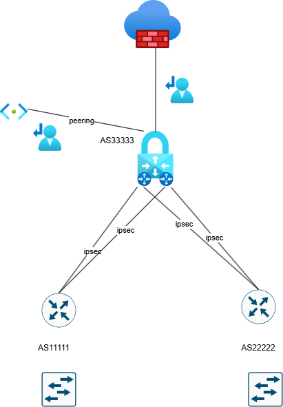
Hello, Can someone explain how Azure processes the traffic with implemented a VPN gateway in Active Active mode?. Azure firewall premium is also configured. BGP is without preferences. The user route definition is set up to the next hop Azure firewall . Is it possible in this scenario occurs the asymmetric routing with traffic drop by azure firewall ? In my understand is that, if we need to configure User route definition on Gateway subnet to inspect traffic to peering subnet, so the firewall don't see traffic passing through VPN gateway. Traffic going through ipsec tunnels can go different paths and firewall do not interfere because everything is routed to it by user route definition.482Views0likes5Comments