azure firewall
48 Topics
What’s new in Azure Firewall: Recent innovations
Organizations are modernizing their networks while managing a growing mix of applications, protocols, and security requirements. Recent Azure Firewall releases strengthen this journey with simpler traffic routing, expanded protocol support, more flexible application controls, improved health visibility, and higher intrusion-detection performance. This roundup highlights five recent capabilities now available in general availability or public preview. In this update: Explicit proxy, IPv6 support, HTTP header insertion, auto-learn SNAT routes, and IDPS performance improvements. Explicit proxy is now generally available Explicit proxy enables clients and applications to send HTTP and HTTPS traffic directly to Azure Firewall by configuring the firewall as their proxy. Instead of relying only on route-based traffic steering, organizations can use familiar proxy settings to centralize outbound web access through Azure Firewall. This release provides a simpler way to use Azure Firewall as a managed forward proxy. It can help teams consolidate web egress controls, support workloads that natively understand proxy configuration, and transition from traditional proxy appliances without introducing another infrastructure layer. Direct proxy configuration: Configure supported clients and applications to use Azure Firewall for HTTP and HTTPS traffic. Centralized web controls: Apply Azure Firewall policy and application rules to proxied traffic. Operational simplicity: Use a managed Azure service instead of deploying and maintaining separate proxy infrastructure. Migration flexibility: Support environments that already use proxy-aware applications or proxy auto-configuration workflows. For more details, visit - Azure Firewall explicit proxy | Microsoft Learn IPv6 support is now in public preview As address requirements grow and organizations adopt dual-stack architectures, IPv6 support is becoming an important part of cloud network design. Azure Firewall IPv6 support, now in public preview, extends centralized traffic filtering to IPv6 scenarios and helps customers protect applications and networks as they introduce IPv6 connectivity. With this preview, teams can evolve IPv4-only environments toward dual-stack networking while continuing to use Azure Firewall as a central enforcement point. This reduces the need to maintain separate security architectures for IPv4 and IPv6 traffic and provides a more consistent policy and operational model. Secure IPv6 traffic across hybrid environments: Filter east-west and hybrid IPv6 traffic across Azure and on-premises networks. Works seamlessly with IPv6-enabled Azure services: Integrate Azure Firewall into end-to-end IPv6 architectures alongside services like ExpressRoute and Virtual Network. Prepare for the future of networking: Build and secure dual-stack environments today while accelerating your IPv6 adoption journey. For more details, visit -Deploy Azure Firewall in dual stack mode (preview) | Microsoft Learn HTTP header insertion is now generally available HTTP header insertion enables Azure Firewall to add configured headers to HTTP requests that match application rules. This gives security and network teams an additional policy control for communicating trusted context to downstream services without requiring every client or application to add the header itself. The capability can support scenarios where applications use headers to enforce organization-specific access requirements, identify traffic handled by a trusted network path, or apply downstream controls. Because configuration is centralized in Azure Firewall policy, teams can apply the behavior consistently across matching traffic and reduce application-side changes. Tenant restriction enforcement: Organizations can inject tenant restriction headers into traffic destined for Microsoft Entra ID, helping prevent users from authenticating unauthorized tenants and strengthening identity governance controls. Secure egress for AVD and enterprise workloads: Support AVD, VDI, and enterprise egress scenarios where organizations need web traffic to carry approved tenant or context headers. Security and Compliance Enforcement: Administrators can add organization-specific headers to web traffic to support security policies, compliance requirements, and backend validation workflows. This helps ensure that only approved applications, tenants, or services are accessed through corporate environments. Operational Efficiency: Customers no longer need dedicated proxy devices solely for HTTP header injection. Azure Firewall can now perform header insertion natively as part of the application rule, reducing operational complexity and infrastructure costs. For more details, visit - Azure Firewall HTTP Header Insertion Configuration | Microsoft Learn Auto-learn SNAT routes is now generally available Source network address translation behavior depends on whether Azure Firewall treats a destination as private or public. In complex enterprise and hybrid networks, manually maintaining the private address ranges that should not be source-NATed can become time-consuming and error-prone as the environment changes. Auto-learn SNAT routes simplifies this process by dynamically learning relevant routes through Azure Route Server and using them to update the firewall’s private IP range configuration. This helps Azure Firewall preserve original source addresses for traffic destined to learned private networks while reducing ongoing configuration maintenance. Reduce manual SNAT management : Automatically learn private and registered routes through Azure Route Server, eliminating the need to manually maintain large No-SNAT prefix lists. Preserve source IPs across hybrid networks : Automatically apply learned routes as No-SNAT destinations, helping maintain source IP visibility and predictable routing for internal traffic. For more details, visit- Azure Firewall SNAT private IP address ranges | Microsoft Learn IDPS performance improvements are now generally available Azure Firewall Premium includes signature-based intrusion detection and prevention to identify and block malicious network activity. The latest IDPS performance improvements increase the amount of protected traffic that Azure Firewall Premium can process, helping organizations apply advanced inspection to demanding production workloads. Azure Firewall Premium now supports up to 22 Gbps with TLS inspection and IDPS in Deny mode, and up to 600 Mbps for a single TCP connection when IDPS is enabled in Alert or Deny mode. Actual performance depends on traffic characteristics, rule configuration, enabled features, and deployment conditions. Higher aggregate throughput: Protect larger traffic volumes while using advanced inspection capabilities. Improved single-flow performance: Better support applications that rely on high-throughput TCP connections. Strong prevention posture: Use IDPS Deny mode to actively block matching malicious traffic. Premium-scale security: Apply TLS inspection and IDPS to more bandwidth-intensive enterprise workloads For more details, visit - Azure Firewall performance | Microsoft Learn Building an advanced, more capable cloud firewall Together, these releases expand how Azure Firewall can protect modern networks. Explicit proxy and HTTP header insertion provide more flexible application-layer controls; IPv6 support helps customers evolve toward dual-stack architectures; Auto-learn SNAT routes reduces operational overhead in dynamic and hybrid environments; and IDPS performance improvements extend advanced threat prevention to higher-throughput workloads. Explore these capabilities in Azure Firewall and review the applicable Azure documentation for configuration requirements, supported scenarios, regional availability, and preview terms before enabling them in production environments.1.5KViews1like1Comment
Azure VM Losing Network Connectivity after Doomain Removal
I currently have Azure VM domain joined servers running Server 2019 Std which are being upgraded via an in-place upgrade to Server 2025 Std. After the upgrade I will be un-joining from the domain and then joining a WORKGROUP to allow Entra ID joining of the servers. I have completed this on a non-critical server but upon removing from the domain the server appears to have lost network connectivity and displays a Computer Icon with a flashing cable, then eventually fails. I noticed the Ethernet displays now “Public” so I changed back to “Private” and removed “Network Level Authentication” from RDP. I also removed the Custom DNS server settings that were on the NIC in Azure Portal and set to “Virtual Network Inherited” to allow Azure DNS. Unfortunately, the same events occur time and time again with no network connectivity. I have reset the NIC and network via Powershell and CMD commands as suggested in most Google searches along with recreating the VM NIC in Azure, but still the same! Does anyone have any idea what could be causing the issue and how to resolve it as someone must have experienced similar in the past when unjoining an Azure VM from a corporate domain? I have been directing all traffic from server via the Azure FW using a Route table with a route directing all traffic via Azure FW and associating the subnets being used: Address Prefix: 0.0.0.0/0 - Next Hop type: Virtual Appliance – Next Hop IP address: <IP of Azure FW Private IP> I assume this would remain the same too? Please any advice or suggestions would be greatly appreciated? Thanks267Views0likes2CommentsAzure Firewall explicit proxy is now generally available
We are excited to announce the general availability of explicit proxy in Azure Firewall. This capability brings the familiar explicit proxy configuration model natively to Azure Firewall, enabling applications and browsers to send outbound HTTP and HTTPS traffic directly to the firewall through standard proxy settings. Customers can now gain centralized policy enforcement and visibility while reducing their dependence on self-managed forward proxy appliances. Proxy the traffic you choose—not the entire subnet Traditional route-based steering can require all traffic from a subnet to traverse a firewall. Explicit proxy offers a more targeted model: configure selected applications or browsers to use the Azure Firewall private IP and proxy port, while other traffic continues on its existing route. This application-level control can simplify migrations, reduce unnecessary routing changes, and help teams apply inspection where it matters most. What’s new for general availability A simpler single-port experience: Serve both HTTP and HTTPS destinations through one HTTP explicit proxy endpoint port, reducing client configuration complexity. More secure PAC file access: Retrieve customer-owned proxy auto-configuration files from Azure Blob Storage using a managed identity. PAC files can be up to 256 KB. A streamlined portal workflow: Enable Explicit proxy when creating a Firewall Policy, with added guidance and validation to help prevent common configuration errors. Built for real-world modernization Modernize legacy proxy infrastructure. Use Azure Firewall as the forward proxy endpoint while retaining the explicit proxy model already configured in applications and browsers. This can help organizations consolidate infrastructure and reduce operational overhead associated with self-hosted proxy appliances. Apply selective application-level steering. Direct only the workloads that require centralized inspection through Azure Firewall, without forcing every flow on a subnet through the same path. Secure Azure Arc connectivity in hybrid environments. Organizations using ExpressRoute or VPN can configure Azure Firewall as a forward proxy for Azure Arc-enabled servers, providing an inspected, policy-controlled outbound path to required Azure services without opening direct internet access from corporate networks. How it works Enable explicit proxy in the Azure Firewall Policy and choose the HTTP proxy port used for both HTTP and HTTPS destinations. Configure applications manually with the firewall’s private IP and proxy port or enable proxy auto-configuration. If you use a PAC file, store it in Azure Blob Storage and configure the required managed identity and access permissions. Create an application rule in the Firewall Policy to allow the intended outbound destinations. Get started today Ready to simplify outbound web traffic steering? Explore the Azure Firewall explicit proxy documentation for prerequisites, portal and API configuration steps, PAC file guidance, and supported scenarios. With explicit proxy now generally available, Azure Firewall gives organizations another flexible path to modernize secure egress—combining a familiar proxy model with the simplicity, scale, and centralized management of a cloud-native service.928Views1like0CommentsSimplify secure, zone-resilient outbound connectivity with Azure Firewall and StandardV2 NAT Gateway
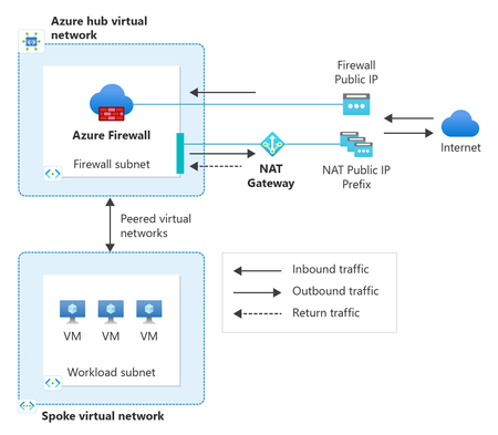
As organizations modernize their applications in Azure, secure and resilient outbound connectivity has become just as critical as inbound security. Workloads need reliable access to external APIs, SaaS services, operating system updates, and partner endpoints, while still meeting strong security controls, predictable egress IPs, and high availability. Achieving all of this consistently requires using the right networking services together. To make this easier, we’ve updated the Azure Firewall create experience in the Azure portal to include StandardV2 NAT Gateway directly in the deployment flow. This new experience makes it quick and seamless to adopt a secure, scalable, and zone‑resilient outbound architecture from day one by using Azure Firewall and Azure NAT Gateway together. In this post, we’ll cover: Why pairing Azure Firewall with StandardV2 NAT Gateway is a recommended design How this combination simplifies secure and resilient outbound connectivity What’s new in the Azure Firewall portal experience and how to get started Why Azure Firewall and StandardV2 NAT Gateway? Azure Firewall and Azure NAT Gateway are designed to complement each other, each focusing on what they do best: Azure Firewall provides centralized traffic inspection and policy enforcement, including IP address and FQDN filtering, threat intelligence, and logging. StandardV2 NAT Gateway delivers high‑scale outbound SNAT, static egress IPs, and built‑in zone redundancy. StandardV2 NAT Gateway is zone‑redundant by default, automatically spanning availability zones within a region. This means outbound connectivity remains available even during a zonal failure without requiring multiple zonal NAT gateways or additional routing configurations. Together, this pairing cleanly separates: Security policy and inspection handled by Azure Firewall Outbound scale, resiliency, and IP predictability handled by NAT Gateway This separation is key for modern, large‑scale cloud workloads. A recommended outbound architecture In a typical hub‑and‑spoke design: Workloads in spoke virtual networks route outbound traffic to Azure Firewall in the hub Firewall policies inspect and allow the traffic StandardV2 NAT Gateway is attached to the AzureFirewallSubnet in the Hub Approved traffic flows through StandardV2 NAT Gateway for SNAT Traffic exits Azure using static, predictable public IPs This approach provides several important benefits: Scalable SNAT capacity for high‑connection workloads Static outbound IPs for partner allow‑listing and compliance Zone‑resilient outbound connectivity by default For step-by-step architectural guidance, see Integrate NAT gateway with Azure Firewall in a hub and spoke architecture. Built for secure and resilient Azure environments As customers increasingly adopt availability zones, large‑scale VMSS or AKS deployments, and zero‑trust network models, outbound connectivity must be secure, predictable, and resilient. By pairing Azure Firewall with StandardV2 NAT Gateway—and now surfacing this pairing directly in the portal create experience—customers can start with a production‑ready outbound architecture that scales with their environment. What's new in the Azure Firewall create experience in the portal When creating a new Azure Firewall in the portal, customers can now: Select and associate a StandardV2 NAT Gateway during firewall deployment. Reduce post‑deployment configuration and manual touches. Start with a recommended zone-resilient outbound architecture by default. By bringing NAT Gateway directly into the Firewall create flow, the portal helps guide customers toward a more secure and scalable outbound setup—without requiring them to stitch services together after the fact. Get started You can try the updated experience today by creating a new Azure Firewall in the Azure portal and selecting StandardV2 NAT Gateway during deployment. With just a couple clicks of a button: In the Basics tab, configure your Firewall settings (ex., SKU, policy, virtual network). In the *new* Advanced tab, create a new or add an existing StandardV2 NAT gateway and associate StandardV2 public IP addresses or prefixes. The StandardV2 NAT gateway is automatically attached to the Firewall subnet—no additional routing or configuration required. Review and Create. Note: StandardV2 NAT Gateway is not yet available in all regions. If your selected region does not support StandardV2 NAT Gateway, the option to enable StandardV2 NAT gateway will not appear during Firewall creation. Refer to StandardV2 NAT Gateway limitations for more information. For more details, see: Integrate StandardV2 NAT Gateway with Azure Firewall Integrate NAT Gateway with Azure Firewall in a hub‑and‑spoke network Azure NAT Gateway SKUs362Views0likes0Comments
Traffic processing BGP Azure VPN gateway A/A
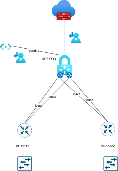
Hello, Can someone explain how Azure processes the traffic with implemented a VPN gateway in Active Active mode?. Azure firewall premium is also configured. BGP is without preferences. The user route definition is set up to the next hop Azure firewall . Is it possible in this scenario occurs the asymmetric routing with traffic drop by azure firewall ? In my understand is that, if we need to configure User route definition on Gateway subnet to inspect traffic to peering subnet, so the firewall don't see traffic passing through VPN gateway. Traffic going through ipsec tunnels can go different paths and firewall do not interfere because everything is routed to it by user route definition.482Views0likes5CommentsHelp! - How is VNet traffic reaching vWAN/on‑prem when the VNet isn’t connected to the vWAN hub
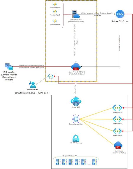
Hello, I needed some clarity on how the following is working: Attached is a network diagram of our current setup. The function apps (in VNet-1) initiate a connection(s) to a specific IP:Port or FQDN:Port in the on-premises network(s). A Private DNS zone ensures that any FQDN is resolved to the correct internal IP address of the on-prem endpoint. In our setup, both the function app and the external firewall reside in the same VNet. This firewall is described as “Unattached” because it is not the built-in firewall of a secured vWAN hub, but rather an independent Azure Firewall deployed in that VNet. The VNet has a user-defined default route (0.0.0.0/0) directing all outbound traffic to the firewall’s IP. The firewall then filters the traffic, allowing only traffic destined to whitelisted on-premises IP: Port or FQDN: Port combinations (using IP Groups), and blocking everything else. The critical question and the part that I am unable to figure out is: Once the firewall permits a packet, how does Azure know to route it to the vWAN hub and on to the site-to-site VPN? Because VNet-1 truly has no connection at all to the vWAN hub (no direct attachment, no peering, no VPN from the NVA). But the traffic is still reaching the on-prem sites. Unable to figure out how this is happening. Am I missing something obvious? Any help on this would be appreciated. Thank you!535Views0likes4CommentsAzure Firewall explicit proxy Migration Guide
Purpose of the blog This blog outlines the key upcoming changes to Azure Firewall explicit proxy and provides detailed migration guidance for customers using PAC file–based configurations. It also covers the supported deployment options for enabling explicit proxy after the changes are released, including the Azure portal, PowerShell, and Azure CLI. Who is this article for? This article is intended for customers currently using Azure Firewall explicit proxy in preview. If you use PAC file–based proxy configuration, follow the steps below to configure the new PAC file SAS URL retrieval method, which will become the standard approach going forward. Azure Firewall explicit proxy Azure Firewall operates in a transparent proxy mode by default. In this mode, you use a user-defined route (UDR) configuration to send traffic to the firewall. The firewall intercepts that traffic inline and passes it to the destination. When you set up explicit proxy on the outbound path, you can configure a proxy setting on the sending application (such as a web browser) with Azure Firewall configured as the proxy. As a result, traffic from the sending application goes to the firewall's private IP address and therefore egresses directly from the firewall without using a UDR. The Azure Firewall explicit proxy feature is in Preview at the time this article was published. Upcoming changes to the explicit proxy feature in Azure Firewall PAC (Proxy Auto-Configuration) file size is now limited to 256 KB. Support HTTP and HTTPS traffic over a single HTTP proxy port. Removal of the previous dual-port configuration requirement (explicit proxy v1). Ability to enable explicit proxy directly using Firewall Policy creation in the Azure portal. Following general availability (GA), explicit proxy will require both a PAC file SAS URL and Managed Identity (MSI), along with the appropriate role assignments to meet Microsoft security standards. Follow the steps below to migrate to the new PAC file retrieval model that uses customer-managed Azure Storage and Managed Identity authentication. Step 1: Create a PAC File SAS URL Create an Azure Storage container by following the steps in Manage blob containers using the Azure portal - Azure Storage | Microsoft Learn. Note: Use a subscription in which required permissions to add roles exist. Upload the PAC file to the storage container. Select the uploaded file and copy the file URL. Example URL: "https://eproxypstestresources.blob.core.windows.net/explicitproxycontainer/proxy.pac" Step 2: Create a Managed Identity and assign required roles Navigate to Managed Identity blade and create a Managed Identity. See Manage user-assigned managed identities using the Azure portal - Managed identities for Azure resources | Microsoft Learn for more details. Go to the storage account resource created in the previous step and navigate to Access Control (IAM). Select Add to add the role assignment. Go to the Add role assignment page and search for Storage Blob Data Contributor and Storage Blob Data Reader, then select both. Go to Members → Managed Identity and select the identity created earlier. Review the changes and click Assign in Review + Assign blade. Verify that your changes are reflected under Role Assignments by searching for the managed identity. Note: Make sure that the Managed Identity created has prefix "PacFileMSI-". Configuration using portal, PowerShell and Azure CLI Portal configuration After obtaining the PAC file SAS URL and Managed Identity, enable the PAC file in the explicit proxy configuration by: providing the PAC file SAS URL, and selecting the Managed Identity created in the previous steps. PowerShell configuration To securely use explicit proxy, customers must provide: the PAC file SAS URL, and a Managed Identity with the required permissions to access the PAC file from the customer-managed Blob Storage account. Create Firewall Policy with explicit proxy settings: $exProxy = New-AzFirewallPolicyExplicitProxy ` -EnableExplicitProxy ` -HttpPort 100 ` -EnablePacFile ` -PacFilePort 130 ` -PacFile "https://sampleurlfortesting.blob.core.windows.net/container/proxy.pac" Update Firewall Policy with explicit proxy configuration: New-AzFirewallPolicy ` -Name "fp1" ` -ResourceGroupName "TestRg" ` -ExplicitProxy $exProxy ` -UserAssignedIdentityId "/subscriptions/e7eb2257-46e4-4826-94df-153853fea38f/resourcegroups/testrg/providers/Microsoft.ManagedIdentity/userAssignedIdentities/PacFileMSI-eproxyidentity" Azure CLI configuration Create Firewall Policy with explicit proxy settings: az network firewall policy create -g "testrg" -n "testfwpolicy" --sku Premium --explicit-proxy enable-explicit-proxy=true http-port=9001 enable-pac-file=true pac-file-port=122 pac-file="https://eproxypstestresources.blob.core.windows.net/explicitproxycontainer/proxy.pac" --identity "Identity_ID" Update Firewall Policy with Explicit Proxy Configuration: az network firewall policy update -g "testrg" -n "testfwpolicy" --explicit-proxy enable-explicit-proxy=true http-port=9001 enable-pac-file=true pac-file-port=124 pac-file="https://eproxypstestresources.blob.core.windows.net/explicitproxycontainer/proxy.pac" --identity "Identity_ID"1.2KViews0likes0Comments
Understanding and building an Azure Hybrid Meshed Hub-Spoke Topology
A meshed hybrid hub-spoke topology Azure offers two main approaches to build network architectures. This article focuses on traditional networking (using VNets, peering, route tables, etc.), rather than Azure Virtual WAN. Why a hub-spoke topology? A hub‑spoke topology is the only way to control traffic flows while maintaining scalability, because it enforces a central point of connectivity and policy enforcement: Centralized traffic control / inspection: All connectivity (to on‑premises, the internet, and between spokes) is anchored through the hub. The hub hosts shared services such as firewalls or NVAs, providing a single control point where traffic is inspected, filtered, and governed consistently. Avoids uncontrolled lateral communication: Spokes do not connect arbitrarily to each other. All connectivity is routed through the hub, preventing uncontrolled east‑west communication and ensuring traffic follows defined security and routing policies. Inherent scalability by design: New workloads are added by introducing additional spokes. The core network design remains unchanged, enabling linear scaling without the complexity of full-mesh connectivity. In summary, the hub‑spoke model provides centralized control combined with scalable, decoupled workload networks—something that flat or full-mesh designs struggle to achieve. From hub-spoke to meshed multi-region In a hub‑spoke topology, it’s important to keep in mind that the hub is implemented as an Azure Virtual Network (VNet) and VNets are scoped to a single region. This means that in a multi‑region setup, you’ll always need at least one hub per region. Each of these hubs hosts shared services like firewalls, NVAs, and DNS, acting as the central point for connectivity and traffic control. Extending dependencies across regions—for example by connecting spokes to a hub in another region—is generally not recommended. It creates tight coupling between regions, which goes against the goal of keeping regions independent. A well-designed multi‑region architecture aims for regional self‑containment to improve resilience and fault isolation. Relying on a remote hub can lead to issues like failure propagation between regions, higher latency for inspected traffic and more complex routing and operations. It can also introduce organizational challenges when different regions are managed by separate teams, reducing agility and increasing operational risk. For this reason, meshed hub‑spoke architectures should use hubs that are deployed within each region. Connectivity between regions should be established directly between the hubs, not through spokes. In a meshed design, hubs are typically connected in a full‑mesh peering model, allowing for controlled and predictable inter‑region communication while still maintaining regional independence. Within a single region, it can also make sense to deploy multiple hubs to create isolated environments. This is especially useful when you need to separate workloads based on security requirements, regulatory needs, or organizational boundaries. Each hub can then have its own dedicated set of connectivity and inspection services. Finally, each spoke VNet connects to just one hub. This keeps routing simple and predictable, ensures that all traffic passes through the correct inspection and policy enforcement layers, and reinforces the hub’s role as the central control point for network traffic within the region. Integrating hybrid connectivity In most enterprise scenarios, Azure doesn’t operate in isolation—it needs to connect to external networks such as on‑premises datacenters or other cloud environments. This hybrid connectivity is typically set up using services like Azure ExpressRoute, Azure VPN Gateway or third‑party SD‑WAN solutions. In a (meshed) hub‑spoke topology, these connectivity components are best deployed in the hub VNet, since the hub acts as the central point where all inbound and outbound traffic comes together. By centralizing external connectivity in the hub, all traffic—whether entering or leaving Azure—can be routed, inspected and governed in a consistent way using shared services like firewalls or NVAs. It also avoids the need to duplicate gateways and connectivity components across multiple spokes, which helps reduce cost and operational overhead. This approach also simplifies routing and policy management. Spokes can rely on the hub’s shared connectivity instead of maintaining their own connections to external networks. Overall, this reinforces the hub’s role as the single, controlled integration point between Azure and the broader network landscape. Implementation fundamentals With the overall architecture in place, the next step is to understand how Azure actually handles routing and traffic control in this kind of design. When working with a hub‑spoke topology in Azure, it’s important to realize that a virtual network (VNet) doesn’t behave like a traditional router. While you can associate Azure Route Tables with subnets, those routes only apply to traffic originating from within that subnet. Traffic entering the VNet from outside isn’t automatically re‑routed. This is also why VNet peering is non‑transitive by design: peered VNets can communicate directly, but they won’t forward traffic for other networks. To enable controlled routing between spokes—and between Azure and external networks such as ExpressRoute or VPN—you need a component in the hub that can actively receive and forward traffic. In most cases, this is handled by an Azure Firewall or a network virtual appliance (NVA) deployed in the hub. These components act as an explicit routing hop: they receive traffic, inspect or process it based on defined policies and then send it back into the virtual network so Azure’s routing engine can continue forwarding it. In a secure hub‑spoke design, the firewall plays a dual role. It not only provides centralized traffic inspection and enforces security policies, but also acts as the mechanism that enables transitive communication between spokes and external networks. This combination of control and connectivity is a key part of the architecture. Of course, this only works as intended if the firewall is configured with the right rules to allow or block traffic according to your security requirements. While it’s technically possible to implement routing using a basic virtual machine or even a Virtual Network Gateway, these approaches don’t meet typical enterprise requirements. They lack built‑in capabilities like advanced traffic inspection, high availability, autoscaling and centralized policy management. Purpose‑built solutions such as Azure Firewall or mature third‑party NVAs are designed to provide not just routing, but also integrated security, consistency, and scalability. For that reason, they’re generally the only realistic choice for production‑grade hub‑spoke environments where both control and resilience matter. Design principles for building the topology The diagram below shows the topology for a hybrid meshed hub-spoke, with 2 hubs and an Azure Firewall (any other 3rd party Firewall could be used as well). Ensuring correct connectivity in a hub-and-spoke topology may initially appear complex, but in practice it comes down to understanding and correctly applying four key design principles: controlled routing in the GatewaySubnet controlled routing in each spoke proper peering of spokes to the hub meshing the hubs. Before looking at these in detail, it is important to understand a fundamental behavior of Azure Virtual Network (VNet) peering. When two VNets are peered, Azure automatically exchanges their address spaces (CIDR ranges) and injects these prefixes as system routes into the effective route tables of all subnets. As a result, resources in one VNet can communicate directly with resources in the other using private IP addressing, without any additional routing configuration. This built-in route propagation is what makes VNet peering an efficient and low-latency connectivity mechanism in Azure. However, this default behavior is not always aligned with the requirements of a hub-and-spoke topology. In this model, network services such as firewalls, inspection and routing control are typically centralized in the hub VNet. If communication between spokes is allowed to follow the automatically injected system routes, traffic could bypass these centralized controls, which would undermine design objectives such as inspection, segmentation and governance. For this reason, although VNet peering provides seamless connectivity by default, additional configuration is required in a hub-and-spoke architecture. This is usually achieved through Azure Route Tables, network virtual appliances (NVAs) or Azure Firewall, ensuring that traffic between spokes is routed through the hub as intended. This approach enables a controlled routing model that is essential for maintaining security and architectural consistency in enterprise-scale Azure environments. Design principle 1: Controlled routing in the GatewaySubnet In hybrid connectivity scenarios, traffic originating from on-premises environments over VPN or ExpressRoute is first terminated by the Azure Virtual Network Gateway. From there, the traffic is injected into the Azure network using the routing context of the GatewaySubnet. By default, this process relies on system routes that are automatically populated through VNet peering. As a result, when the destination resides in a spoke VNet, the traffic is forwarded directly to that spoke, since its address space has already been learned and installed as a system route. While this behavior is efficient, it also means that traffic will bypass centralized security controls in the hub, such as Azure Firewall. To ensure that all incoming traffic is properly inspected, this default routing behavior needs to be adjusted. This is done by associating a custom Azure Route Table with the GatewaySubnet and defining user-defined routes for each spoke address range. These routes should point to the private IP address of the firewall as the next hop, effectively overriding the system routes created by VNet peering. Because Azure gives precedence to user-defined routes over system routes, traffic that would normally go directly to the spoke is instead redirected through the firewall before reaching its destination. It is important that these user-defined routes precisely match the CIDR ranges defined for the spoke VNets! Any mismatch, such as using broader or more specific prefixes, can lead to unexpected routing behavior and may introduce issues such as asymmetric traffic flows or packet loss. For instance, if a spoke uses address spaces like 10.10.10.0/24 and 192.168.10.0/24, these exact prefixes must be reflected in the route table. Only by aligning the custom routes with the advertised address ranges can you ensure predictable routing and consistent inspection through the firewall. If the hub VNet hosts additional resources beyond an Azure Firewall or third-party network virtual appliance that also require traffic inspection, the corresponding CIDR ranges—either for the specific subnets or for the entire hub VNet—should be included as routes in the route table associated with the GatewaySubnet. These routes should be configured in the same way as those for spoke VNets, ensuring that traffic destined for these resources is directed through the intended inspection point. A typical example is Azure DNS Private Resolver, which can include both inbound and outbound endpoints deployed in dedicated subnets. When such endpoints are present in the hub, their associated subnet address ranges must also be added to the route table for the GatewaySubnet. This ensures that traffic to and from these endpoints is routed through the designated inspection path, maintaining consistent enforcement of security controls. Design principle 2: Controlled routing in every spoke In a hub-and-spoke architecture, traffic flows should follow the intended security model. Workloads within the same spoke VNet are usually treated as part of the same trust boundary, so traffic between resources in that spoke can flow directly over the Azure backbone without needing to pass through centralized controls. Network Security Groups (NSGs) should still be used at the subnet level to provide granular, stateful filtering, but routing this traffic through a central firewall is typically not required. The situation changes when traffic leaves the local VNet. As soon as traffic is destined for another spoke, the hub, or on-premises networks, it crosses a trust boundary and needs to be inspected centrally. To enforce this, Azure’s default routing behavior must be overridden by associating an Azure Route Table with each subnet in the spoke VNets. In most cases, this route table can be kept simple by defining a single default route that sends all outbound, non-local traffic to the firewall in the hub: Destination: 0.0.0.0/0 Next hop: Private IP address of the hub firewall (Virtual Appliance) With this configuration in place, all traffic that is not local to the spoke is forced through the hub, ensuring that communication between VNets and towards external networks is inspected and controlled. From a management perspective, the same route table can often be reused across multiple subnets or even multiple VNets within the same subscription, which helps keep the design consistent and easy to maintain. It’s worth noting, however, that Azure requires route tables and the subnets they’re associated with to be in the same subscription, as this association is enforced by the platform. There is one additional setting that is often overlooked but plays an important role in getting routing right in a hub-and-spoke design. Azure route tables include an option called “Propagate gateway routes”, which controls whether routes learned by a Virtual Network Gateway are added to the effective routes of the associated subnets. By default, routes learned via BGP (for example from ExpressRoute or VPN) or defined through a Local Network Gateway are propagated not only within the hub VNet, but also across VNet peerings. This means that spoke VNets can automatically learn routes to on-premises or external networks and may send traffic directly to the gateway, bypassing the firewall in the hub. To avoid this and keep traffic flowing through the centralized security controls, this setting should be disabled on the route tables used by the spoke subnets. When “Propagate gateway routes” is set to No, routes learned by the gateway are no longer injected into the spokes. As a result, traffic to those destinations cannot take a direct path and instead follows the user-defined default route (0.0.0.0/0) toward the hub firewall, where it can be properly inspected. When combined with the default route to the firewall, this setup ensures that traffic—whether it is going to other VNets, on-premises environments, or external networks—always follows a controlled and predictable path through the hub. This helps maintain consistent security enforcement and avoids unexpected routing behavior in larger or hybrid deployments. Design principle 3: Peering the spokes to the hub Virtual Network (VNet) peering in Azure is often seen as a simple, single configuration, but in reality it is directional by design. To fully connect two VNets, you need two separate peering configurations—one in each direction—and both must be configured correctly to ensure not only connectivity, but also proper routing behavior. Each peering exposes four key settings and getting these right is especially important in a hub-and-spoke architecture. For basic connectivity, the first two settings—“allow virtual network access” and “allow forwarded traffic”—should be enabled on both peerings. These ensure that traffic can flow between VNets and support scenarios where traffic is routed through a central component, such as a firewall in the hub. The other two settings depend on the direction of the peering. In a typical hub-and-spoke setup, the Virtual Network Gateway (or Azure Route Server) is deployed in the hub. This means the peering from the spoke to the hub must enable “use remote gateways”, while the peering from the hub to the spoke must enable “allow gateway transit.” At first, this might seem to contradict the idea that spokes should not directly use the gateway. However, these settings influence control plane behavior and don't enable unrestricted traffic flow. They are required so the gateway can learn and advertise spoke address ranges via BGP to external networks, such as those connected over VPN or ExpressRoute. Whether those routes are actually used in the spokes is still controlled through the “propagate gateway routes” setting on the route tables, allowing you to enforce routing through the firewall as intended. Even if you are not currently using BGP—for example, in environments relying on static routing—it is still a good practice to configure peerings this way. Doing so makes the design future-proof, allowing you to introduce dynamic routing later without changes to the peering model. This approach keeps the architecture consistent and avoids unnecessary rework as the environment evolves. Design principle 4: Meshing the hubs When you extend a hub-and-spoke design across multiple regions, you typically introduce multiple hubs, each managing its own regional spokes. In this setup, it becomes important to connect the hubs to each other, which is done by fully meshing the hub VNets using VNet peering. At the same time, a key principle remains unchanged: each spoke should connect to only one hub in the same region. This keeps the architecture simple, scalable and easier to reason about from a routing perspective. When configuring connectivity between hubs, it’s important to note that VNet peering settings differ from the typical hub–spoke configuration. For inter-hub peerings, only “allow virtual network access” and “allow forwarded traffic” should be enabled. The remaining options—“allow gateway transit” and “use remote gateways”—should be left disabled, as gateway sharing is not required between hubs and would even be blocked in the configuration. Just connecting the hubs with peering is not enough to guarantee correct traffic flow. To ensure traffic moves between regions in a controlled and secure way, you need additional routing logic. Each hub should have an Azure Route Table assigned to its FirewallSubnet (or the subnet hosting the 3rd party NVAs) defining how traffic towards other hub-and-spoke environments is handled. This ensures that inter-region traffic is always routed through the appropriate hub firewall, instead of flowing directly across the Azure backbone. At this point, IP address planning becomes critical. Without a clear addressing strategy, routing quickly becomes complex and hard to maintain. A common best practice is to assign a single “master” CIDR range per region, and then allocate all VNets in that region—both hub and spokes—from that range. This creates a clean, hierarchical addressing model that simplifies routing decisions. With this approach in place, route tables can remain relatively simple. Instead of adding routes for every individual spoke, you only need one route per remote region. The destination is the master CIDR range of that region and the next hop is the private IP of the firewall in the corresponding hub. Because all hubs are peered with each other, these address ranges and firewall endpoints are automatically known through peering, allowing for consistent and predictable routing. Overall, this design keeps routing logic straightforward while ensuring that all inter-region traffic is inspected in the correct hub, preserving the security model and making it easy to scale as new regions are added. Conclusion When the four design principles described in this article are applied consistently, a hub-and-spoke architecture becomes a strong, scalable and easy-to-operate foundation for your network. By combining controlled routing, centralized inspection and clear traffic flows, the model delivers both solid security and predictable behavior, even in complex environments. More importantly, the concepts covered here go beyond just one specific design. They represent the key building blocks of Azure networking, including routing, peering and traffic control. Understanding these fundamentals not only helps you implement hub-and-spoke topologies correctly, but also gives you a solid base for designing and running reliable, enterprise-grade network architectures in Azure. To make this easier to apply in practice, the table below summarizes the main concepts from this article and how they translate into actual configuration. It can be useful both when setting up a hub-and-spoke topology and when troubleshooting existing environments. Area Configuration Key Setting / Value Purpose Hub VNet Deploy shared services Azure Firewall or NVA in hub Central inspection + routing Deploy connectivity VPN Gateway / ExpressRoute in hub Centralize hybrid connectivity GatewaySubnet Associate Route Table UDRs for each spoke CIDR → Firewall IP Force inbound traffic through firewall Spoke Subnets Associate Route Table 0.0.0.0/0 → Firewall (Virtual Appliance) Force all outbound traffic via hub Route Table setting Propagate gateway routes = Disabled Prevent bypass of firewall via gateway VNet Peering (Spoke → Hub) Setting Allow VNet access = Yes Basic connectivity Setting Allow forwarded traffic = Yes Support transitive routing via firewall Setting Allow gateway transit = Yes Allow spoke to leverage hub gateway Setting Use remote gateways = No - VNet Peering (Hub → Spoke) Setting Allow VNet access = Yes Basic connectivity Setting Allow forwarded traffic = Yes Support routing through firewall Setting Allow gateway transit = No - Setting Use remote gateways = Yes Advertise spoke prefixes via hub gateway VNet Peering (Hub→ Hub) Setting Allow VNet access = Yes Basic connectivity Setting Allow forwarded traffic = Yes Support transitive routing via firewall Setting Allow gateway transit = No - Setting Use remote gateways = No - Hub FirewallSubnet Associate Route Table Route remote region CIDR → remote hub firewall IP Ensure inter-region/hub routing Addressing strategy CIDR planning Assign master CIDR per region Simplify routing and reduce UDR complexity Spoke design rule Peering constraint Each spoke connected to one hub only Prevent routing ambiguity1.4KViews2likes2Comments
Spoke-Hub-Hub Traffic with VPN Gateway BGP and Firewall Issue
Hello, I’m facing a situation where I’m trying to have Azure Firewall Inspection on the VPN Gateway VNET-VNET Connectivity. It seems to work if I go from SpokeA-HubAFirewall-HubAVPN—HubBVPN-SpokeB but if I try to go from SpokeA-HubAFirewall-HubAVPN-HubBVM or Inbound Resolver it fails to route correctly according to Connectivity Troubleshooter it stops at HubAVPN with Local Error: RouteMissing but then reaches destination health so makes me believe it’s getting there but not following the route I want it to take which might be causing routing issues. What Am I missing here? This connectivity was working before introducing the Azure Firewall for Inspection with the UDR. Is what I’m trying to accomplish not possible? I’ve tried different types of UDR rules on the Gateway Subnet, and this is my most recent configuration. The reason I’m trying to accomplish this is because I’m seeing a similar error in our Hub-Spoke Hybrid environment and I’m trying to replicate the issue. Current Configuration 2x Hubs with Spoke networks attached so example Hub-Spoke-A Configuration: Hub-A Contains following subnets and Resources VPN Gateway - GateWaySubnet Azure Firewall - AzureFirewallSubnet Inbound Private Resolver - PrivateResolverSubnet Virtual Machine – VM Subnet Gateway Subnet has an attached UDR with the following routes Propagation - True Prefix Destination – Hub-B Next Hop Type – Virtual Appliance Next Hope IP – Hub-A Firewall Prefix Destination – Spoke-B Next Hop Type – Virtual Appliance Next Hope IP – Hub-A Firewall Hub-Spoke-B Configuration: Hub-B Contains following subnets and Resources VPN Gateway - GateWaySubnet Azure Firewall - AzureFirewallSubnet Inbound Private Resolver - PrivateResolverSubnet Virtual Machine – VM Subnet Gateway Subnet has an attached UDR with the following Routes Propagation - True Prefix Destination – Hub-A Next Hop Type – Virtual Appliance Next Hope IP – Hub-B Firewall Prefix Destination – Spoke-A Next Hop Type – Virtual Appliance Next Hope IP – Hub-B Firewall Spoke Subnets has an attached UDR with the following Routes Propagation - True Prefix Destination – 0.0.0.0/0 Next Hop Type – Virtual Appliance Next Hope IP – HubA/HubB Firewall (Depending on what hub its peered to) VPN Gateways HA VNET-VNET with BGP Enabled. I can see that it knows the routes and like I said this was working prior introducing the UDRs for force traffic through the azure firewall.599Views0likes2CommentsDeploying Third-Party Firewalls in Azure Landing Zones: Design, Configuration, and Best Practices
As enterprises adopt Microsoft Azure for large-scale workloads, securing network traffic becomes a critical part of the platform foundation. Azure’s Well-Architected Framework provides the blueprint for enterprise-scale Landing Zone design and deployments, and while Azure Firewall is a built-in PaaS option, some organizations prefer third-party firewall appliances for familiarity, feature depth, and vendor alignment. This blog explains the basic design patterns, key configurations, and best practices when deploying third-party firewalls (Palo Alto, Fortinet, Check Point, etc.) as part of an Azure Landing Zone. 1. Landing Zone Architecture and Firewall Role The Azure Landing Zone is Microsoft’s recommended enterprise-scale architecture for adopting cloud at scale. It provides a standardized, modular design that organizations can use to deploy and govern workloads consistently across subscriptions and regions. At its core, the Landing Zone follows a hub-and-spoke topology: Hub (Connectivity Subscription): Central place for shared services like DNS, private endpoints, VPN/ExpressRoute gateways, Azure Firewall (or third-party firewall appliances), Bastion, and monitoring agents. Provides consistent security controls and connectivity for all workloads. Firewalls are deployed here to act as the traffic inspection and enforcement point. Spokes (Workload Subscriptions): Application workloads (e.g., SAP, web apps, data platforms) are placed in spoke VNets. Additional specialized spokes may exist for Identity, Shared Services, Security, or Management. These are isolated for governance and compliance, but all connectivity back to other workloads or on-premises routes through the hub. Traffic Flows Through Firewalls North-South Traffic: Inbound connections from the Internet (e.g., customer access to applications). Outbound connections from Azure workloads to Internet services. Hybrid connectivity to on-premises datacenters or other clouds. Routed through the external firewall set for inspection and policy enforcement. East-West Traffic: Lateral traffic between spokes (e.g., Application VNet to Database VNet). Communication across environments like Dev → Test → Prod (if allowed). Routed through an internal firewall set to apply segmentation, zero-trust principles, and prevent lateral movement of threats. Why Firewalls Matter in the Landing Zone While Azure provides NSGs (Network Security Groups) and Route Tables for basic packet filtering and routing, these are not sufficient for advanced security scenarios. Firewalls add: Deep packet inspection (DPI) and application-level filtering. Intrusion Detection/Prevention (IDS/IPS) capabilities. Centralized policy management across multiple spokes. Segmentation of workloads to reduce blast radius of potential attacks. Consistent enforcement of enterprise security baselines across hybrid and multi-cloud. Organizations May Choose Depending on security needs, cost tolerance, and operational complexity, organizations typically adopt one of two models for third party firewalls: Two sets of firewalls One set dedicated for north-south traffic (external to Azure). Another set for east-west traffic (between VNets and spokes). Provides the highest security granularity, but comes with higher cost and management overhead. Single set of firewalls A consolidated deployment where the same firewall cluster handles both east-west and north-south traffic. Simpler and more cost-effective, but may introduce complexity in routing and policy segregation. This design choice is usually made during Landing Zone design, balancing security requirements, budget, and operational maturity. 2. Why Choose Third-Party Firewalls Over Azure Firewall? While Azure Firewall provides simplicity as a managed service, customers often choose third-party solutions due to: Advanced features – Deep packet inspection, IDS/IPS, SSL decryption, threat feeds. Vendor familiarity – Network teams trained on Palo Alto, Fortinet, or Check Point. Existing contracts – Enterprise license agreements and support channels. Hybrid alignment – Same vendor firewalls across on-premises and Azure. Azure Firewall is a fully managed PaaS service, ideal for customers who want a simple, cloud-native solution without worrying about underlying infrastructure. However, many enterprises continue to choose third-party firewall appliances (Palo Alto, Fortinet, Check Point, etc.) when implementing their Landing Zones. The decision usually depends on capabilities, familiarity, and enterprise strategy. Key Reasons to Choose Third-Party Firewalls Feature Depth and Advanced Security Third-party vendors offer advanced capabilities such as: Deep Packet Inspection (DPI) for application-aware filtering. Intrusion Detection and Prevention (IDS/IPS). SSL/TLS decryption and inspection. Advanced threat feeds, malware protection, sandboxing, and botnet detection. While Azure Firewall continues to evolve, these vendors have a longer track record in advanced threat protection. Operational Familiarity and Skills Network and security teams often have years of experience managing Palo Alto, Fortinet, or Check Point appliances on-premises. Adopting the same technology in Azure reduces the learning curve and ensures faster troubleshooting, smoother operations, and reuse of existing playbooks. Integration with Existing Security Ecosystem Many organizations already use vendor-specific management platforms (e.g., Panorama for Palo Alto, FortiManager for Fortinet, or SmartConsole for Check Point). Extending the same tools into Azure allows centralized management of policies across on-premises and cloud, ensuring consistent enforcement. Compliance and Regulatory Requirements Certain industries (finance, healthcare, government) require proven, certified firewall vendors for security compliance. Customers may already have third-party solutions validated by auditors and prefer extending those to Azure for consistency. Hybrid and Multi-Cloud Alignment Many enterprises run a hybrid model, with workloads split across on-premises, Azure, AWS, or GCP. Third-party firewalls provide a common security layer across environments, simplifying multi-cloud operations and governance. Customization and Flexibility Unlike Azure Firewall, which is a managed service with limited backend visibility, third-party firewalls give admins full control over operating systems, patching, advanced routing, and custom integrations. This flexibility can be essential when supporting complex or non-standard workloads. Licensing Leverage (BYOL) Enterprises with existing enterprise agreements or volume discounts can bring their own firewall licenses (BYOL) to Azure. This often reduces cost compared to pay-as-you-go Azure Firewall pricing. When Azure Firewall Might Still Be Enough Organizations with simple security needs (basic north-south inspection, FQDN filtering). Cloud-first teams that prefer managed services with minimal infrastructure overhead. Customers who want to avoid manual scaling and VM patching that comes with IaaS appliances. In practice, many large organizations use a hybrid approach: Azure Firewall for lightweight scenarios or specific environments, and third-party firewalls for enterprise workloads that require advanced inspection, vendor alignment, and compliance certifications. 3. Deployment Models in Azure Third-party firewalls in Azure are primarily IaaS-based appliances deployed as virtual machines (VMs). Leading vendors publish Azure Marketplace images and ARM/Bicep templates, enabling rapid, repeatable deployments across multiple environments. These firewalls allow organizations to enforce advanced network security policies, perform deep packet inspection, and integrate with Azure-native services such as Virtual Network (VNet) peering, Azure Monitor, and Azure Sentinel. Note: Some vendors now also release PaaS versions of their firewalls, offering managed firewall services with simplified operations. However, for the purposes of this blog, we will focus mainly on IaaS-based firewall deployments. Common Deployment Modes Active-Active Description: In this mode, multiple firewall VMs operate simultaneously, sharing the traffic load. An Azure Load Balancer distributes inbound and outbound traffic across all active firewall instances. Use Cases: Ideal for environments requiring high throughput, resilience, and near-zero downtime, such as enterprise data centers, multi-region deployments, or mission-critical applications. Considerations: Requires careful route and policy synchronization between firewall instances to ensure consistent traffic handling. Typically involves BGP or user-defined routes (UDRs) for optimal traffic steering. Scaling is easier: additional firewall VMs can be added behind the load balancer to handle traffic spikes. Active-Passive Description: One firewall VM handles all traffic (active), while the secondary VM (passive) stands by for failover. When the active node fails, Azure service principals manage IP reassignment and traffic rerouting. Use Cases: Suitable for environments where simpler management and lower operational complexity are preferred over continuous load balancing. Considerations: Failover may result in a brief downtime, typically measured in seconds to a few minutes. Synchronization between the active and passive nodes ensures firewall policies, sessions, and configurations are mirrored. Recommended for smaller deployments or those with predictable traffic patterns. Network Interfaces (NICs) Third-party firewall VMs often include multiple NICs, each dedicated to a specific type of traffic: Untrust/Public NIC: Connects to the Internet or external networks. Handles inbound/outbound public traffic and enforces perimeter security policies. Trust/Internal NIC: Connects to private VNets or subnets. Manages internal traffic between application tiers and enforces internal segmentation. Management NIC: Dedicated to firewall management traffic. Keeps administration separate from data plane traffic, improving security and reducing performance interference. HA NIC (Active-Passive setups): Facilitates synchronization between active and passive firewall nodes, ensuring session and configuration state is maintained across failovers. This design choice is usually made during Landing Zone design, balancing security requirements, budget, and operational maturity. : NICs of Palo Alto External Firewalls and FortiGate Internal Firewalls in two sets of firewall scenario 4. Key Configuration Considerations When deploying third-party firewalls in Azure, several design and configuration elements play a critical role in ensuring security, performance, and high availability. These considerations should be carefully aligned with organizational security policies, compliance requirements, and operational practices. Routing User-Defined Routes (UDRs): Define UDRs in spoke Virtual Networks to ensure all outbound traffic flows through the firewall, enforcing inspection and security policies before reaching the Internet or other Virtual Networks. Centralized routing helps standardize controls across multiple application Virtual Networks. Depending on the architecture traffic flow design, use appropriate Load Balancer IP as the Next Hop on UDRs of spoke Virtual Networks. Symmetric Routing: Ensure traffic follows symmetric paths (i.e., outbound and inbound flows pass through the same firewall instance). Avoid asymmetric routing, which can cause stateful firewalls to drop return traffic. Leverage BGP with Azure Route Server where supported, to simplify route propagation across hub-and-spoke topologies. : Azure UDR directing all traffic from a Spoke VNET to the Firewall IP Address Policies NAT Rules: Configure DNAT (Destination NAT) rules to publish applications securely to the Internet. Use SNAT (Source NAT) to mask private IPs when workloads access external resources. Security Rules: Define granular allow/deny rules for both north-south traffic (Internet to VNet) and east-west traffic (between Virtual Networks or subnets). Ensure least privilege by only allowing required ports, protocols, and destinations. Segmentation: Apply firewall policies to separate workloads, environments, and tenants (e.g., Production vs. Development). Enforce compliance by isolating workloads subject to regulatory standards (PCI-DSS, HIPAA, GDPR). Application-Aware Policies: Many vendors support Layer 7 inspection, enabling controls based on applications, users, and content (not just IP/port). Integrate with identity providers (Azure AD, LDAP, etc.) for user-based firewall rules. : Example Configuration of NAT Rules on a Palo Alto External Firewall Load Balancers Internal Load Balancer (ILB): Use ILBs for east-west traffic inspection between Virtual Networks or subnets. Ensures that traffic between applications always passes through the firewall, regardless of origin. External Load Balancer (ELB): Use ELBs for north-south traffic, handling Internet ingress and egress. Required in Active-Active firewall clusters to distribute traffic evenly across firewall nodes. Other Configurations: Configure health probes for firewall instances to ensure faulty nodes are automatically bypassed. Validate Floating IP configuration on Load Balancing Rules according to the respective vendor recommendations. Identity Integration Azure Service Principals: In Active-Passive deployments, configure service principals to enable automated IP reassignment during failover. This ensures continuous service availability without manual intervention. Role-Based Access Control (RBAC): Integrate firewall management with Azure RBAC to control who can deploy, manage, or modify firewall configurations. SIEM Integration: Stream logs to Azure Monitor, Sentinel, or third-party SIEMs for auditing, monitoring, and incident response. Licensing Pay-As-You-Go (PAYG): Licenses are bundled into the VM cost when deploying from the Azure Marketplace. Best for short-term projects, PoCs, or variable workloads. Bring Your Own License (BYOL): Enterprises can apply existing contracts and licenses with vendors to Azure deployments. Often more cost-effective for large-scale, long-term deployments. Hybrid Licensing Models: Some vendors support license mobility from on-premises to Azure, reducing duplication of costs. 5. Common Challenges Third-party firewalls in Azure provide strong security controls, but organizations often face practical challenges in day-to-day operations: Misconfiguration Incorrect UDRs, route tables, or NAT rules can cause dropped traffic or bypassed inspection. Asymmetric routing is a frequent issue in hub-and-spoke topologies, leading to session drops in stateful firewalls. Performance Bottlenecks Firewall throughput depends on the VM SKU (CPU, memory, NIC limits). Under-sizing causes latency and packet loss, while over-sizing adds unnecessary cost. Continuous monitoring and vendor sizing guides are essential. Failover Downtime Active-Passive models introduce brief service interruptions while IPs and routes are reassigned. Some sessions may be lost even with state sync, making Active-Active more attractive for mission-critical workloads. Backup & Recovery Azure Backup doesn’t support vendor firewall OS. Configurations must be exported and stored externally (e.g., storage accounts, repos, or vendor management tools). Without proper backups, recovery from failures or misconfigurations can be slow. Azure Platform Limits on Connections Azure imposes a per-VM cap of 250,000 active connections, regardless of what the firewall vendor appliance supports. This means even if an appliance is designed for millions of sessions, it will be constrained by Azure’s networking fabric. Hitting this cap can lead to unexplained traffic drops despite available CPU/memory. The workaround is to scale out horizontally (multiple firewall VMs behind a load balancer) and carefully monitor connection distribution. 6. Best Practices for Third-Party Firewall Deployments To maximize security, reliability, and performance of third-party firewalls in Azure, organizations should follow these best practices: Deploy in Availability Zones: Place firewall instances across different Availability Zones to ensure regional resilience and minimize downtime in case of zone-level failures. Prefer Active-Active for Critical Workloads: Where zero downtime is a requirement, use Active-Active clusters behind an Azure Load Balancer. Active-Passive can be simpler but introduces failover delays. Use Dedicated Subnets for Interfaces: Separate trust, untrust, HA, and management NICs into their own subnets. This enforces segmentation, simplifies route management, and reduces misconfiguration risk. Apply Least Privilege Policies: Always start with a deny-all baseline, then allow only necessary applications, ports, and protocols. Regularly review rules to avoid policy sprawl. Standardize Naming & Tagging: Adopt consistent naming conventions and resource tags for firewalls, subnets, route tables, and policies. This aids troubleshooting, automation, and compliance reporting. Validate End-to-End Traffic Flows: Test both north-south (Internet ↔ VNet) and east-west (VNet ↔ VNet/subnet) flows after deployment. Use tools like Azure Network Watcher and vendor traffic logs to confirm inspection. Plan for Scalability: Monitor throughput, CPU, memory, and session counts to anticipate when scale-out or higher VM SKUs are needed. Some vendors support autoscaling clusters for bursty workloads. Maintain Firmware & Threat Signatures: Regularly update the firewall’s software, patches, and threat intelligence feeds to ensure protection against emerging vulnerabilities and attacks. Automate updates where possible. Conclusion Third-party firewalls remain a core building block in many enterprise Azure Landing Zones. They provide the deep security controls and operational familiarity enterprises need, while Azure provides the scalable infrastructure to host them. By following the hub-and-spoke architecture, carefully planning deployment models, and enforcing best practices for routing, redundancy, monitoring, and backup, organizations can ensure a secure and reliable network foundation in Azure.4.2KViews5likes2Comments