Welcome to the third installment of Network Virtualization in Virtual Machine Manager! This series will be an example-based walkthrough consisting of a few parts:
-
http://blogs.technet.com/b/scvmm/archive/2013/11/27/adopting-network-virtualization-part-i.aspx
-
http://blogs.technet.com/b/scvmm/archive/2013/11/27/adopting-network-virtualization-part-ii.aspx
-
Part III: Adding External Connectivity to Virtualized Networks (This post)
-
Part IV: Flattening the VLAN Topology
-
Part V: Expanding to Hybrid Scenarios
-
Part VI: Technical Details
In this post, I’ll be introducing a network virtualization gateway. As previously discussed, VM networks that use network virtualization will be completely isolated and do not have external communication. We’ll be fixing that in this post. It is possible to create a VM running a software router and give it two NICs, attaching one to the VM network and one to the external network. However, this scenario is not supported by Microsoft, does not provide any integration with VMM, and can only be used by a single tenant.
First, we’ll need a cluster that sits on the edge of our network to house the VMs that will act as a gateway. I created a cluster named EDGECLUSTER running Windows Server 2012 R2 with a Server Core installation and it has two nodes named CON-HyperV8 and CON-HyperV9. The cluster has a witness disk and a sufficiently large CSV. Moving forward, I’ll assume you’ve done the same, as I won’t be discussing cluster creation in this series.
I’ve already added my EDGECLUSTER to VMM just as in the previous posts. In PowerShell:
|
001
002 |
$edgeGroup = New-SCVMHostGroup -Name "Edge" -ParentHostGroup $allHostsGroup;
$edgeCluster = Add-SCVMHostCluster -Name "EDGECLUSTER.contoso.com" -VMHostGroup $edgeGroup -Credential $domainAdminRAA -RemoteConnectEnabled $true; |
Refer to my previous posts if you need GUI instructions.
Understanding Network Virtualization Gateways
Before beginning configuration, we should discuss how a network virtualization gateway functions. A network virtualization gateway is a specific VM that will act as a Layer3 device to allow traffic flow to an external network.

The gateway itself is controlled by VMM from the management network and will forward traffic from an NVGRE network to an external network. As such, the gateway requires connectivity to all three networks.
The gateway can function as a NAT device, a forwarding device, and can provide a site-to-site VPN tunnel. In this post, I’ll only be discussing deploying the gateway as a NAT device to provide external connectivity to tenants. When I discuss hybrid cloud connectivity in a future post, I’ll cover the other capabilities.
Desired Topology
At this point, my physical networking topology looks like this:

Each host has two NICs that are assigned as trunk ports in the switch. I want my logical topology to look like this:

Management Network (Thin Solid Line)
Connects to all hosts and is used for VMM communication.
Tenant Network(s) (Dashed Line)
These are the networks we created in the previous post (we actually only created one) to isolate tenants using VLANs. These networks are not needed on the management cluster or the virtualization cluster.
Virtualization Network(s) (Dotted Line)
These networks exist as a logical entity through network virtualization. Each network is segregated but uses the same VLAN for transport. From a Layer-2 perspective, there is only a single network and the segregation is enforced higher in the network stack. In this post, we’ll be adding external connectivity to this network.
External Network (Thick Solid Line)
This network is the connection to another network for the virtualized traffic. Although I’m using an external network, this network could also be something else, like a corporate network.
In the diagram above, notice that the EDGECLUSTER has three networks. The network virtualization gateways will reside on these hosts and will connect to all three of these networks. But first, we’ll need to create the networking objects in VMM. The host clusters in my VMM server look like this:
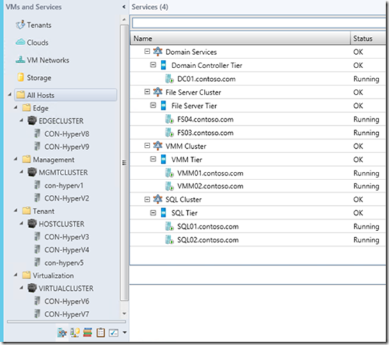
All of my VMs that perform management (AD, File Cluster, VMM Cluster, and SQL Cluster) reside on my MGMTCLUSTER. My HOSTCLUSTER has tenant VMs whose networks are segregated using VLANs, my VIRTUALCLUSTER has tenant VMs segregated via network virtualization, and my EDGECLUSTER is currently not configured, as it’s just been added.
Of the three networks on my EDGECLUSTER, two already exist: the virtualization network and the management network. We’ll want to create the third network for external traffic and create a logical switch whose associated uplink port profile connect to all three networks. So, let’s begin.
Creating Networking Components
First, the external network. In my environment, this is VLAN 801, so I’ll configure that. As before, start the Create Logical Network Wizard . Name the network External .

Next, create the network site and apply it to the Edge group, and provide the IP information.

Finish the wizard to create the Logical Network. In PowerShell:
|
001
002 003 |
$extLogicalNetwork = New-SCLogicalNetwork -Name "External" -LogicalNetworkDefinitionIsolation $false -EnableNetworkVirtualization $false -UseGRE $false -IsPVLAN $false;
$extSubnetVlan = New-SCSubnetVLan -Subnet "10.80.1.0/24" –VLanID 801; $extLogicalNetworkDefinition = New-SCLogicalNetworkDefinition -Name "External" -LogicalNetwork $extlogicalNetwork -VMHostGroup $edgeGroup -SubnetVLan $extSubnetVlan; |
I’ll need to create my Uplink Port Profile next, but I first need to update the host group for the Virtualization network. When we configured the Virtualization Logical Network, we only assigned its network site to the Virtualization host group. To add the Edge group, simply bring up the properties of the Virtualization network.

On the Network Site tab, select the Edge network and click OK .

Now the Virtualization Logical Network can be associated with a host in the Edge group via an Uplink Port Profile. We didn’t have to do this step for the Management network because its network site is set to the All Hosts group. In PowerShell:
|
001
|
Set-SCLogicalNetworkDefinition -LogicalNetworkDefinition $virtualizationLogicalNetworkDefinition -AddVMHostGroup $edgeGroup;
|
Now to create the Uplink Port Profile. Start the Create Hyper-V Port Profile wizard as in previous posts and name it Edge , choosing Uplink port profile as the type.

For the Network Configuration , check the boxes next to the three networks that the EDGECLUSTER needs: External , Management , and Virtualization .

Finish the wizard to create the Uplink Port Profile. In PowerShell:
|
001
|
$edgeUplinkPortProfile = New-SCNativeUplinkPortProfile -Name "Edge" -LogicalNetworkDefinition @($mgmtLogicalNetworkDefinition, $extLogicalNetworkDefinition, $virtualizationLogicalNetworkDefinition) -EnableNetworkVirtualization $true -LBFOLoadBalancingAlgorithm "HostDefault" -LBFOTeamMode "SwitchIndependent";
|
Now we create the Logical Switch called Edge and assign it the Edge Uplink Port Profile. This is the same as previous posts, so I won’t walk through the steps. In PowerShell:
|
001
002 003 |
$edgeLogicalSwitch = New-SCLogicalSwitch -Name "Edge" -EnableSriov $false -SwitchUplinkMode "Team";
$edgeUplinkPortProfileSetGUID = [System.Guid]::NewGuid().toString(); $edgeUplinkPortProfileSet = New-SCUplinkPortProfileSet -Name "Edge_$edgeUplinkPortProfileSetGUID" -LogicalSwitch $edgeLogicalSwitch -NativeUplinkPortProfile $edgeUplinkPortProfile; |
Next, we’ll create the VM Network. There is nothing special about this in the GUI. Just create a new VM Network named External and assign it to the External Logical Network. In PowerShell:
|
001
|
$extVMNetwork = New-SCVMNetwork -Name "External" -LogicalNetwork $extLogicalNetwork -IsolationType "NoIsolation";
|
Lastly, we need to add the Logical Switch to the hosts. I’ve covered the GUI for these steps before in previous posts. I’ll defer the PowerShell for a moment, as there is something else that needs to be done.
One last configuration step is to enable the hosts in my EDGECLUSTER to be dedicated as gateway hosts. To do this, bring up the properties of the host and find the Host Access tab. Here, you’ll find a checkbox for This host is a dedicated network virtualization gateway…. that you’ll need to check:

This will need to be done on all the hosts in EDGECLUSTER. In PowerShell, we’ll do this while adding the Logical Switch to the host:
|
001
002 003 004 005 006 007 008 009 010 011 012 013 014 015 |
$nodeNames = $edgeCluster.Nodes.Name;
$nodeIPs = @{}; foreach($name in $nodeNames) { $nodeIPs[$name] = @([System.Net.Dns]::GetHostAddresses($name).IPAddressToString)[0]; } foreach($node in $edgeCluster.Nodes) { $jobgroupGUID = [System.Guid]::NewGuid().ToString(); $firstNetworkAdapter = Get-SCVMHostNetworkAdapter -VMHost $node | ?{$_.IPAddresses -contains $nodeIPs[$node.Name]}; Set-SCVMHostNetworkAdapter -VMHostNetworkAdapter $firstNetworkAdapter -UplinkPortProfileSet $edgeUplinkPortProfileSet -JobGroup $jobgroupGUID; $otherNetworkAdapters = Get-SCVMHostNetworkAdapter -VMHost $node | ?{$_.IPAddresses -notcontains $nodeIPs[$node.Name]}; $otherNetworkAdapters | %{Set-SCVMHostNetworkAdapter -VMHostNetworkAdapter $_ -UplinkPortProfileSet $edgeUplinkPortProfileSet -JobGroup $jobgroupGUID}; $networkAdapters = @($firstNetworkAdapter, $otherNetworkAdapters); New-SCVirtualNetwork -VMHost $node -VMHostNetworkAdapters $networkAdapters -LogicalSwitch $edgeLogicalSwitch -JobGroup $jobgroupGUID -CreateManagementAdapter -ManagementAdapterName "Management" -ManagementAdapterVMNetwork $mgmtVMNetwork; Set-SCVMHost -VMHost $node -IsDedicatedToNetworkVirtualizationGateway $true -JobGroup $jobgroupGUID; } |
Notice the Set-SCVMHost cmdlet includes the parameter – IsDedicatedToNetworkVirtualizationGateway that we set to true.
That’s all for host configuration. Now on to deploying the gateway.
Importing the Gateway Template
The System Center Virtual Machine Manager product team has provided a service template for deploying a network virtualization gateway. You can download the ZIP http://download.microsoft.com/download/0/D/1/0D189100-07B7-4CBF-B774-7A3F43960145/Windows%20Server%202012%20R2%20HA%20Gateway.zip .
The ZIP contains a document that outlines the process, but I’ll be going through it here as well. First, you’ll need to have a sysprep’d disk image in your VMM Library containing Windows Server 2012 R2 (I won’t be covering this step). You’ll also need two empty disk images in your library for the cluster disks. Lastly, you’ll need to import the custom resource included with the template. Once you have that, you can import the template.
First, create the disks. This is simplest in PowerShell via a command like:
|
001
002 |
New-VHD -Path "C:\Users\domainadmin\CSV.vhdx" -SizeBytes 10GB -Dynamic;
New-VHD -Path "C:\Users\domainadmin\Quorum.vhdx" -SizeBytes 1GB -Dynamic; |
Next, you’ll need to import the resources. To import, in the Library pane, click the Import Physical Resource button on the Home ribbon.
In the dialog, click the Add custom resource… button to browse to the folder called VMClusterSetup.cr that was included with the ZIP. Do this again for each disk that was earlier created, this time clicking Add resource… . Next, click the Browse… button to identify the VMM Library location where the resource will be copied. Once that’s all populated, click Import .

In PowerShell, this would be something like (your paths will vary):
|
001
002 003 |
Import-SCLibraryPhysicalResource -SourcePath "C:\Users\domainadmin\Downloads\Windows Server 2012 R2 HA Gateway\VMClusterSetup.cr\" -SharePath "\\FILESHARE.Contoso.com\VMMLibrary";
Import-SCLibraryPhysicalResource -SourcePath "C:\Users\domainadmin\Downloads\Windows Server 2012 R2 HA Gateway\CSV.vhdx" -SharePath "\\FILESHARE.Contoso.com\VMMLibrary"; Import-SCLibraryPhysicalResource -SourcePath "C:\Users\domainadmin\Downloads\Windows Server 2012 R2 HA Gateway\Quorum.vhdx" -SharePath "\\FILESHARE.Contoso.com\VMMLibrary"; |
Note that, depending on your certificate configuration, you may have to check the Use unencrypted transfer checkbox. In PowerShell, this is the flag – AllowUnencryptedTransfer for each command. Once the resource is imported, you can import the template.
To import a template in VMM, in the Library pane, click the Import Template button on the Home ribbon.

In the wizard, click Browse… and find the extracted location. Select the Windows Server 2012 HA Gateway 3NIC.xml file and click Open and then Next . On the next page, you’ll identify the specific resource mappings. For any mapping, you can click the pencil icon to select the appropriate resource in the Library. Once finished, click Next .

Finish the wizard to import the template. The PowerShell equivalent of this can be a bit tricky. You’ll have to create a template package, create a package mapping, add each resource to the mapping, and then call the Import-SCTemplate on that package object and its mapping. The PowerShell below is a loose guidelines that you might have to tweak for your environment:
|
001
002 003 004 005 006 007 008 009 010 011 012 013 014 015 016 017 018 019 020 |
$package = Get-SCTemplatePackage -Path "C:\Users\domainadmin\Downloads\Windows Server 2012 R2 HA Gateway\Windows Server 2012 R2 HA Gateway 3NIC.xml";
$allMappings = New-SCPackageMapping -TemplatePackage $package; # Mapping for VMClusterSetup.cr $mapping = $allMappings | ?{$_.PackageId -eq "VMClusterSetup.cr"}; $resource = Get-SCCustomResource -Name "VMClusterSetup.cr"; Set-SCPackageMapping -PackageMapping $mapping -TargetObject $resource; # Mapping for Win2012R2.vhdx $mapping = $allMappings | ?{$_.PackageId -eq "Win2012R2.vhdx"}; $resource = Get-SCVirtualHardDisk -Name "WindowsServerR2.vhdx"; Set-SCPackageMapping -PackageMapping $mapping -TargetObject $resource; # Mapping for CSV.vhdx $mapping = $allMappings | ?{$_.PackageId -eq "CSV.vhdx"}; $resource = Get-SCVirtualHardDisk -Name "CSV.vhdx"; Set-SCPackageMapping -PackageMapping $mapping -TargetObject $resource; # Mapping for Quorum.vhdx $mapping = $allMappings | ?{$_.PackageId -eq "Quorum.vhdx"}; $resource = Get-SCVirtualHardDisk -Name "Quorum.vhdx"; Set-SCPackageMapping -PackageMapping $mapping -TargetObject $resource; # Import Template $gwTemplate = Import-SCTemplate -TemplatePackage $package -Name "Windows Server 2012 R2 HA Gateway - 3NIC" -PackageMapping $allMappings -Release "1.0" -SettingsIncludePrivate; |
Once imported, we can deploy the template.
Environment Requirements for the Gateway Template
There are few requirements for deploying the gateway template. Each of these requirements reflect the supported configuration for the gateway that was tested by the product team. I’ll speak to possible workarounds for these requirements, but I won’t go through their configuration details.
First, the NIC that connects to the external network is configured to use a static IP. As such, you’ll need a static IP pool in VMM. If you wish to use DHCP, you’ll need to edit the template and change this.
Next, the template uses shared storage but is not configured as highly available (HA). Since VMs that are not HA cannot use CSV for shared storage, you’ll need to configure a Scale-Out File Server. The reasoning behind not making this template HA was likely to disallow automatic VM failover. As an alternative, you could mark this template as HA and configure the available nodes on the cluster role for the VM after deployment.
Lastly, the storage classification for the OS drive for the template is marked as Local Storage . If you don’t have any local volumes on your hosts that are available for placement, you might want to just clear the classification for that drive in the template.
Deploying the Gateway Template
To deploy a template in VMM, in the Library pane, expand Templates and click Service Templates , and then right-click the template we just imported and select Configure Deployment .

Supply the name Gateway and select the appropriate VM networks. The Infrastructure network is the network that the VMM server will use to communicate with this VM (in my environment, this is Management ) and the External network is the outgoing connection for the virtualization traffic (in my environment, this is External ). Click OK to proceed.

Once the deployment window appears, populate the required settings and click the Refresh Preview button to allow VMM to run placement and decide which hosts the VMs should be deployed to.

After running placement, you should be ready to deploy. Be sure that when choosing the name for the cluster, you choose a name that does not exist in DNS and that it is less than the NetBIOS restriction of 15 characters. Note that I did not include a static IP address for the cluster.

Click the Deploy Service button to begin the deployment.
In PowerShell, deploying a service is somewhat more involved. You’ll need to create a service configuration object, populate its service settings, run placement on the configuration object, and deploy the configuration object, which creates a service instance. Here is a PowerShell script meant to be a guide:
|
001
002 003 004 005 006 007 008 009 010 011 012 013 014 015 016 017 018 019 020 021 022 023 024 025 026 027 028 029 030 031 032 033 034 035 036 037 038 039 040 041 042 043 044 |
$gwTemplate = Get-SCServiceTemplate -Name "Windows Server 2012 R2 HA Gateway - 3NIC";
$edgeGroup = Get-SCVMHostGroup -Name "Edge"; # Configurable service settings $serviceSettingsMap = @{}; $serviceSettingsMap.Add("DomainFQDN", "contoso.com"); $serviceSettingsMap.Add("VMClusterStaticIPAddress", ""); $serviceSettingsMap.Add("LocalAdmin", $(Get-SCRunAsAccount -Name "Local Admin")); $serviceSettingsMap.Add("Infrastructure", $(Get-SCVMNetwork -Name "Management").ID); $serviceSettingsMap.Add("VMClusterName", "HAGW01CLUSTER"); $serviceSettingsMap.Add("DomainUserRAAName", $($domainRAA.Domain + "\" + $domainRAA.UserName)); # Hidden in this post $serviceSettingsMap.Add("ProductKey", "XXXXX-XXXXX-XXXXX-XXXXX-XXXXX"); $serviceSettingsMap.Add("DomainUserRAA", $(Get-SCRunAsAccount -Name "Domain Admin")); $serviceSettingsMap.Add("External", $(Get-SCVMNetwork -Name "External").ID); # Create a new configuration object $serviceConfig = New-SCServiceConfiguration -Name "Gateway" -ServiceTemplate $gwTemplate -VMHostGroup $edgeGroup; # Set the required network settings for network mappings $serviceSettings = Get-SCServiceSetting -ServiceConfiguration $serviceConfig; foreach($setting in $serviceSettings) { Set-SCServiceSetting -ServiceSetting $setting -Value $serviceSettingsMap[$setting.Name] | Out-Null; } # Run placement $serviceUpdate = Update-SCServiceConfiguration -ServiceConfiguration $serviceConfig; # Verify placement succeeded if($serviceUpdate.DeploymentErrorList.Count -ne 0) { Write-Host "Placement failure." -ForegroundColor Red; break; } # Deploy template $deployedService = New-SCService -ServiceConfiguration $serviceConfig -RunAsynchronously; # Monitor job progress (not really robust, doesn't handle failure) [System.Threading.Thread]::Sleep(1000); $job = $deployedService.GetMostRecentJob(); while($job.Status -eq "Running") { Write-Progress -Activity $("Deploying " + $job.ResultName) -Status $job.Description -PercentComplete $job.ProgressValue; Write-Progress -Id 1 -Activity "Current Subtask" -Status $job.CurrentStep.Description -PercentComplete $job.CurrentStep.ProgressValue; } |
This script isn’t incredibly robust or well-tested; it’s just meant to give you an idea of the process so you can write your own script. Once deployment has completed, you’ll have a Gateway service running.
Next, we need to connect VMM to this gateway.
Adding the Virtualization Gateway as a Network Service
VMM will need to communicate with the gateway (hence the management connection) to configure it. To do this, we’ll add the gateway as a Network Service to VMM. To create a Network Service, in the Fabric pane, expand Networking , right-click Network Service , and select Add Network Service .

On the first page of the wizard, name the service NAT Gateway .

On the next page, select Microsoft Windows Server Gateway as the Model .

Provide the appropriate Run As Account on the next page. This account needs to either match the account you supplied for the template or another account with appropriate rights.

Continue to the Connection String page. When a provider is installed on the VMM server, the provider author provides a library for VMM to use that contains a set of callback functions. The connection string is provided as input to these functions, and these functions parse the string. As such, VMM does not dictate the format of the string; it’s provider-specific.
For the Gateway Provider, the connection string must follow the pattern Parameter1=Value1;Paramter2=Value2;…;ParameterN=ValueN . The possible parameters are:
| Setting | Required | Description |
| VMHost | Yes | FQDN of the Hyper-V host cluster. |
| GatewayVM | Yes | FQDN of the VM cluster. |
| BackendSwitch | No | Name of virtual switch using network virtualization. |
| DirectRoutingMode | No | True to make this a forwarding gateway, False for VPN or NAT (default). |
| FrontEndServerAddress | No* |
IP address of the frontend for this gateway. This should be the next hop address for external devices routing to this network.
* = Required if DirectRoutingMode=True. |
| VPNServerAddress | No | IP address of the interface for this VPN endpoint. |
| MaxVMNetworksSupported | No | Maximum VM networks used with a gateway. The default is 50 and the maximum is 100. Note that if DirectRoutingMode=True, this can only be 1. |
In my environment, I’ll use:
VMHost=EDGECLUSTER.contoso.com;GatewayVM=HAGW01CLUSTER.contoso.com;BackendSwitch=Edge
You can supply this string in the field and click Next :

Continue to the Provider page and click the Test button to verify configuration.

Continue to the Host Group page and select Virtualization and Edge .

Finish the wizard to add the network service. In PowerShell, you might want to do this in two steps. First, test the configuration:
|
001
002 003 |
$configurationProvider = Get-SCConfigurationProvider -Name "Microsoft Windows Server Gateway Provider";
$connectionString = "VMHost=EDGECLUSTER.contoso.com;GatewayVM=HACLUSTER.contoso.com;BackendSwitch=Edge"; Test-SCNetworkGateway -ConnectionString $connectionString -RunAsAccount $domainAdminRAA -ConfigurationProvider $configurationProvider; |
That should give you output like this:

Providing you get a True for all but MarkedForDeletion and IsViewOnly , you can proceed to add the gateway:
|
001
|
$gwService = Add-SCNetworkService -Name "NAT Gateway" -RunAsAccount $domainAdminRAA -ConfigurationProvider $configurationProvider -VMHostGroup @($edgeGroup, $virtualizationGroup) -ConnectionString $connectionString;
|
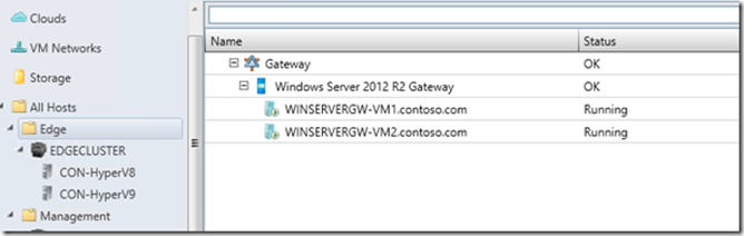
Now you should have a gateway:

The next step is configuring the networks to use this new gateway.
Configuring the Network Virtualization Gateway
First, open the properties of the gateway and click on the Connectivity page. Select the appropriate adapters. The Frontend network will be the External connection and the Backend will be the Virtualization network. The template has already populated information based on the NIC names that were generated in the template scripts. In my environment, my External network is corporate domain corp.microsoft.com. I’ll select the NIC corresponding to that connection for my frontend network. For the backend network, I’ll select the NIC that the template scripts labeled as BackEnd . My settings look like this:
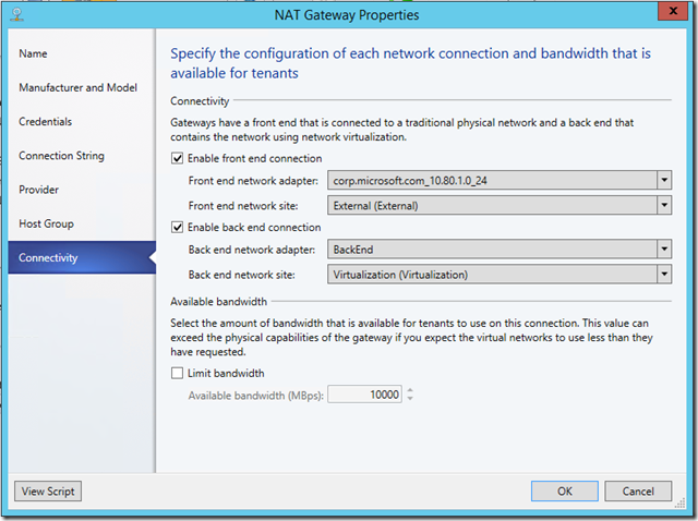
After clicking OK , VMM will configure the appropriate settings and connect the vNICs to the proper networks through the Management adapter. In PowerShell:
|
001
002 003 004 005 |
$frontEndAdapter = $gwService.NetworkAdapters | ?{$_.AdapterName -like "*10.80.1.0*"};
Add-SCNetworkConnection -Name "Front End" -LogicalNetworkDefinition $extLogicalNetworkDefinition -Service $gwService -NetworkAdapter $frontEndAdapter -ConnectionType FrontEnd | Out-Null; $backEndAdapter = $gwService.NetworkAdapters | ?{$_.AdapterName -eq "BackEnd"}; Add-SCNetworkConnection -Name "Back End" -LogicalNetworkDefinition $virtualizationLogicalNetworkDefinition -Service $gwService -NetworkAdapter $backEndAdapter -ConnectionType BackEnd | Out-Null; Set-SCNetworkService -NetworkService $gwService; |
Now that we have all those components in place, we simply need to add the gateway to a VM Network using network virtualization for isolation.
Connecting VM Networks
First, bring up the properties of the VM Network using network virtualization. If you’ve been following my posts, you might recall I have Fabrikam2 and Fabrikam3 as isolated VM Networks on the Virtualization network. I’ll bring up the properties of Fabrikam2 . On the Connectivity page, some options now appear. We’ll select Connect directly to an additional logical network and choose Network address translation (NAT) as the gateway type.

You can see some statistics around remaining capacity and information about the gateway device. Note that the gateway device lists its capabilities based on the provider capabilities, not the actual configuration. In a future post, I’ll get into configuring each capability.
You can click OK to make the changes. At this point, VMM will configure the gateway to connect its NIC to the virtualization network and create all the routing necessary to make connectivity happen. In PowerShell,
|
001
002 003 |
$fabrikam2VMNetworkGateway = Add-SCVMNetworkGateway -Name "Fabrikam2_Gateway" -EnableBGP $false -NetworkGateway $gwService -VMNetwork $fabrikam2VMNetwork;
$extStaticIPPool = Get-SCStaticIPPool -LogicalNetworkDefinition $extLogicalNetworkDefinition; Add-SCNATConnection -Name "Fabrikam2_NatConnection" -VMNetworkGateway $fabrikam2VMNetworkGateway -ExternalIPPool $extStaticIPPool; |
If you have existing VMs, they should now have external connectivity. In order to successfully resolve DNS, the IP pool assigned to the virtualized network will need DNS servers. You can either deploy a DNS server within the virtualized network, or you can simply supply external IP addresses for DNS servers.
Next Time
In the next post, we’ll be cleaning up the environment and flattening the VLAN topology to get a converged fabric, making things easier to manage and making onboarding of new servers simple. I hope you’re finding this series helpful. Feel free to offer any requests for content. If you want to read about, someone else does, too.
Technical Details
If you’ve been following this series, you’ll notice I added a Part VI that will be related to technical details. I’ve had feedback from readers to go into more technical content, so I’ll be planning that post as a follow-up to this series. I’ll try to make that post as comprehensive as possible, but leave a comment if there are any specific components you want the details about.