This is the second post in a series about transitioning from using VLANs for tenant segregation to Network Virtualization. This series will be an example-based walkthrough consisting of a few parts:
- Part I: Configuration with VLAN Segregation
- Part II: VLANs with Network Virtualization (This post)
- Part II: Adding External Connectivity to Virtualized Networks
- Part IV: Flattening the VLAN Topology
- Part V: Expanding to Hybrid Scenarios
In the previous post , we configured a brand new environment and brought in VLANs to segregate network traffic between VM Networks. In this post, I’ll introduce the concept of Virtualized Networking and explain how to bring it into our environment. For some of the tasks I perform in this post, I’ll be skipping UI instructions that I’ve covered in a previous post.
Getting Started
I’ll assume we’ve followed steps outlined in the previous post and have a environment configured as such. If things have been operating with VLAN segregation and tenants VMs have been deployed to the tenant VM Networks, we’ll want to take the least disruptive route to introducing network virtualization.
To this end, I’ll be adding another cluster to my environment for tenants with virtualized networking environments. In this environment, I have seven hosts in three clusters. As before, all my hosts each have two NICs that are configured as trunk ports in the switch they connect to with the management network as the native VLAN. The physical cabling and cluster membership is depicted below:

As before, my HOSTCLUSTER is using VLANs to segregate its tenant traffic. My VIRTUALCLUSTER, however, will be using network virtualization to segregate tenants. My goal will be to create the network topology represented below:

Management Network (Solid Line)
Connects to all hosts and is used for VMM communication.
Tenant Network(s) (Dashed Line)
These are the networks we created in the previous post (we actually only created one) to isolate tenants using VLANs. These networks are not needed on the management cluster or the virtualization cluster. If you’ve deleted the configuration for the HOSTCLUSTER already, you won’t have this network.
Virtualization Network(s) (Dotted Line)
These networks exist as a logical entity through network virtualization. Each network is segregated but uses the same VLAN for transport. From a Layer-2 perspective, there is only a single network and the segregation is enforced higher in the network stack. In this post, the virtualized network will not have external access. We’ll cover connecting these networks to external resources in the next post. Also, we’re using a dedicated VLAN for the virtualization network in this post and we’ll do away with that in a later post.
Adding Hosts
I’ll first need to add the new cluster. Refer to my previous post for detailed instructions on this in the UI. I’ll be creating a new host group called Virtualization and adding a cluster named VIRTUALCLUSTER to it. In PowerShell, this is:
|
001
002 |
$virtualizationGroup = New-SCVMHostGroup -Name "Virtualization" -ParentHostGroup $allHostsGroup;
$virtualizationCluster = Add-SCVMHostCluster -Name "VIRTUALCLUSTER.contoso.com" -VMHostGroup $virtualizationGroup -Credential $domainAdminRAA -RemoteConnectEnabled $true; |
Now, I have my cluster added:

Next, I’ll be configuring a network for network virtualization.
Adding Network Objects
The hosts in my VIRTUALCLUSTER will have connectivity to my virtualization network and to my management network. This is similar to my HOSTCLUSTER configuration. Although logically segregated, the virtualization traffic will be transported (encapsulated) over my management network.
First, I’ll create the logical network. To do this, in the Fabric pane, expand Networking , right-click Logical Networks , and select Create Logical Network .

In the wizard, name the network Virtualization and select Allow new VM networks created on this logical network to use network virtualization .

On the next page, create a network site and add an appropriate VLAN/Subnet for this network:

Finish the wizard to create the logical network. In PowerShell:
|
001
002 003 |
$virtualizationLogicalNetwork = New-SCLogicalNetwork -Name "Virtualization" -LogicalNetworkDefinitionIsolation $false -EnableNetworkVirtualization $true -UseGRE $true -IsPVLAN $false;
$virtualizationSubnetVlan = New-SCSubnetVLan -Subnet "10.80.2.0/24" -VLanID 802; $virtualizationLogicalNetworkDefinition = New-SCLogicalNetworkDefinition -Name "Virtualization" -LogicalNetwork $virtualizationLogicalNetwork -VMHostGroup @($virtualizationGroup) -SubnetVLan $virtualizationSubnetVlan; |
Next, I’ll create an Uplink Port Profile for my VIRTUALCLUSTER that connects to the management network and the virtualization network. In the Fabric pane, expand Networking , right-click Port Profiles and select Create Hyper-V Port Profile .

Name the port profile Virtualization and choose to make it an Uplink Port Profile:

On the next page, we’ll select the site to connect to. The hosts in the VIRTUALCLUSTER will connect to the management site and the Virtualization site, so we’ll select these and select Enable Hyper-V Network Virtualization . In my environment, I’m using only Windows Server 2012 R2 hosts, so I don’t need to select this option, but I’ll select it in case I add Windows Server 2012 hosts in the future.

Finish the wizard to create the Uplink Port Profile. In PowerShell:
|
001
|
$virtualizationUplinkPortProfile = New-SCNativeUplinkPortProfile -Name "Virtualization" -LogicalNetworkDefinition @($mgmtLogicalNetworkDefinition, $virtualizationLogicalNetworkDefinition) -EnableNetworkVirtualization $true -LBFOLoadBalancingAlgorithm "HostDefault" -LBFOTeamMode "SwitchIndependent";
|
Next, I’ll create a Logical Switch for my VIRTUALCLUSTER. In the Fabric pane, expand Networking , right-click Logical Switches and select Create Logical Switch .

In the wizard, on the General page, name the switch Virtualization

On the Uplink page, add the Uplink Port Profile (in PowerShell, this corresponds to creating the Uplink Port Profile Set):

Finish the wizard to create the Logical Switch. In PowerShell:
|
001
002 003 |
$virtualizationLogicalSwitch = New-SCLogicalSwitch -Name "Virtualization" -EnableSriov $false -SwitchUplinkMode "Team";
$virtualizationUplinkPortProfileSetGUID = [System.Guid]::NewGuid().toString(); $virtualizationUplinkPortProfileSet = New-SCUplinkPortProfileSet -Name "Virtualization_$virtualizationUplinkPortProfileSetGUID" -LogicalSwitch $virtualizationLogicalSwitch -NativeUplinkPortProfile $virtualizationUplinkPortProfile; |
Next, I’ll create a Virtualization VM Network. The VM Network that I’ll be creating will be the network that transmits the virtualization traffic, but not a tenant virtualization network. Any Logical Network that uses network virtualization will need a network on which to transmit the encapsulated traffic and can only be associated with one such network. Subsequent tenant networks will all exist on the same logical network. So, first, the transport network. In the VMs and Services pane, right-click VM Networks and select Create VM Network

Name the network Virtualization and select the Virtualization Logical Network that we just created.

On the Isolation page, choose No isolation , since this is the transport network for virtualization traffic.

Finish the wizard to create the VM Network. In PowerShell,
|
001
|
$virtualizationVMNetwork = New-SCVMNetwork -Name "Virtualization" -LogicalNetwork $virtualizationLogicalNetwork -IsolationType "NoIsolation";
|
Now, we can add the Logical Switch to the hosts.
Adding the Logical Switch to Hosts
This is similar to configuring the Logical Switches on the HOSTCLUSTER in the previous post, except that we’ll be adding the Virtualization Logical Switch:

And we’ll be adding an adapter for Management connectivity:

The PowerShell is also similar:
|
001
002 003 004 005 006 007 008 009 010 011 012 013 014 015 |
$nodeNames = $virtualizationCluster.Nodes.Name;
$nodeIPs = @{}; foreach($name in $nodeNames) { $nodeIPs[$name] = @([System.Net.Dns]::GetHostAddresses($name).IPAddressToString)[0]; } foreach($node in $virtualizationCluster.Nodes) { $jobgroupGUID = [System.Guid]::NewGuid().ToString(); $firstNetworkAdapter = Get-SCVMHostNetworkAdapter -VMHost $node | ?{$_.IPAddresses -contains $nodeIPs[$node.Name]}; Set-SCVMHostNetworkAdapter -VMHostNetworkAdapter $firstNetworkAdapter -UplinkPortProfileSet $virtualizationUplinkPortProfileSet -JobGroup $jobgroupGUID; $otherNetworkAdapters = Get-SCVMHostNetworkAdapter -VMHost $node | ?{$_.IPAddresses -notcontains $nodeIPs[$node.Name]}; $otherNetworkAdapters | %{Set-SCVMHostNetworkAdapter -VMHostNetworkAdapter $_ -UplinkPortProfileSet $virtualizationUplinkPortProfileSet -JobGroup $jobgroupGUID}; $networkAdapters = @($firstNetworkAdapter, $otherNetworkAdapters); New-SCVirtualNetwork -VMHost $node -VMHostNetworkAdapters $networkAdapters -LogicalSwitch $virtualizationLogicalSwitch -JobGroup $jobgroupGUID -CreateManagementAdapter -ManagementAdapterName "Management" -ManagementAdapterVMNetwork $mgmtVMNetwork; Set-SCVMHost -VMHost $node -JobGroup $jobgroupGUID | Out-Null; } |
After adding the Logical Switch to all the hosts in the cluster, we’re almost ready to proceed with onboarding Tenants. First, we’ll need some IP addresses for the transport network.
Adding Provider IP Pools
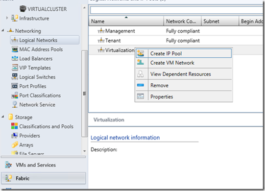
Static IP Pools can be assigned to a logical network so that deployed VMs can have an IP without a DHCP server. It’s a convenient way to manage IP addresses on a network. To create one, in the Fabric pane, expand Networking , select Logical Networks , right-click the Virtualization Logical Network, and select Create IP Pool .
You can name the pool Default and make sure the Virtualization Logical Network is selected.

Select the previously created network site:

Supply the IP range, or leave the defaults:

On the next pages, you can supply additional IP information (Gateway, DNS, WINS), but this is not necessary for this environment, as the VLAN that I’m using does not have any of these components. For now, just complete this wizard to create the IP Pool. In PowerShell:
|
001
|
$virtualizationStaticIPPool = New-SCStaticIPAddressPool -Name "Default" -LogicalNetworkDefinition $virtualizationLogicalNetworkDefinition -Subnet "10.80.2.0/24" -IPAddressRangeStart "10.80.2.1" -IPAddressRangeEnd "10.80.2.254"
|
We have a static IP pool:

And now we can start adding Tenant Networks.
Adding Tenant Networks
In this scenario, we’ll bring in a tenant called Fabrikam2 (no doubt a subsidiary of Fabrikam). With network virtualization, this is as simple as adding a VM Network. So, in the VMs and Services pane, right-click VM Networks , and select Create VM Network .

Name the network Fabrikam2 and select Virtualization for the Logical Network.

On the next page, you’ll choose to Isolate using Hyper-V network virtualization and I’ll be choosing IPv4 for this network.

A quick hiatus: For IP protocols, you’ll notice that you can elect to either choose IPv4 or IPv6 in the tenant environment, but you can only choose IPv4 for the logical network (the transport network created earlier). This is because we only provided an IPv4 address for our network site. If you added an IPv6 address to your network site…

Then you can choose IPv6 transport for the logical network:

Note that dual-stacking is not supported for network virtualization. Moving on, we get to a VM Subnet page. On this page, we will define VM Subnets, which are akin to network sites. Creating VM Subnet allows you to then create a static IP pool for this subnet so your tenant can get a VM. I’ll explain in a moment how the IPs are used by a VM using network virtualization. For now, choose an arbitrary private IP range, as this is an isolated network.

On the connectivity page, you will likely see a notification that the VM Network will have no external connectivity:

This is because there is no gateway device added to VMM. In a later post, I’ll discuss external connectivity. For now, simply finish the wizard. In PowerShell:
|
001
002 003 |
$fabrikam2VMNetwork = New-SCVMNetwork -Name "Fabrikam2" -LogicalNetwork $virtualizationLogicalNetwork -IsolationType "WindowsNetworkVirtualization" -CAIPAddressPoolType "IPV4" -PAIPAddressPoolType "IPV4";
$fabrikam2Subnet = New-SCSubnetVLan -Subnet "192.168.0.0/25"; $fabrikam2VMSubnet = New-SCVMSubnet -Name "Default" -VMNetwork $fabrikam2VMNetwork -SubnetVLan $fabrikam2Subnet; |
We’re almost ready, but the VMs will need IP addresses.
Adding Customer IP Pools
Now is probably a good time to discuss the difference between a Provider Address ( PA ) and a Customer Address ( CA ). The PA is the IP address the VM will use to communicate when passing traffic over the transport network (in our case, the Virtualization VM Network) and the CA is the IP address the VM thinks it has. So, VM1 transmits a packet for VM2.

So the packets from VM1 on 192.168.0.5 destined for VM2 on 192.168.0.6 are encapsulated to be sent as packets from 10.80.2.5 to 10.80.2.6. In this case, the 192.168.0.0 range is the CA space and the 10.80.2.0 range is the PA space. Since the CA space resides in a virtualized network, you can have multiple CA spaces with overlapping subnets on a single PA space. Keep in mind that these numbers are just examples.
We created an IP Pool for the PA space earlier, now we need to create one for the CA space. To do this, in the VMs and Services pane, click VM Networks , right-click Fabrikam2 , and select Create IP Pool .

Just like a IP Pool in the PA space corresponds to a subnet of a Network Site, an IP Pool in the CA space corresponds to a VM Subnet. In the wizard, supply the name Default and continue creating the IP pool as before.

You can accept the default range or supply a different range:

Finish the wizard to create the IP Pool. In PowerShell:
|
001
|
$fabrikam2StaticIPPool = New-SCStaticIPAddressPool -Name "Default" -VMSubnet $fabrikam2VMSubnet -Subnet "192.168.0.0/25" -IPAddressRangeStart "192.168.0.2" -IPAddressRangeEnd "192.168.0.126"
|
Now, we’re ready to deploy Fabrikam2 tenant VMs.
Deploying VMs
I created a VM Template with a Windows Server 2012 R2 and configured the network card to be attached to Fabrikam2 and use static IPs:

I also added some OS Configuration to supply a machine name, Product Key, and local administrator password:

Now, I’ll deploy this VM Template. Although I chose my destination as all hosts, only my hosts that support network virtualization are suitable due to network configurations:

I’ll deploy two VMs. In PowerShell, deploying a VM from a template is similar to the GUI. VMM Generates a temporary hardware profile and a temporary VM template before generating a configuration object, running placement on that object, and then using that configuration object to create a VM. So, the PowerShell equivalent would be:
|
001
002 003 004 005 006 007 008 009 010 011 012 013 014 015 016 017 |
$vmTemplate = Get-SCVMTemplate -Name "Tenant VM";
$jobGroupID = [System.Guid]::NewGuid().ToString(); New-SCVirtualScsiAdapter -JobGroup $jobGroupID -AdapterID 7 -ShareVirtualScsiAdapter $false -ScsiControllerType DefaultTypeNoType; New-SCVirtualDVDDrive -JobGroup $jobGroupID -Bus 1 -LUN 0; New-SCVirtualNetworkAdapter -JobGroup $jobGroupID -MACAddress "00:00:00:00:00:00" -MACAddressType Static -VLanEnabled $false -Synthetic -EnableVMNetworkOptimization $false -EnableMACAddressSpoofing $false -EnableGuestIPNetworkVirtualizationUpdates $false -IPv4AddressType Static -IPv6AddressType Dynamic -VMSubnet $fabrikam2VMSubnet -VMNetwork $fabrikam2VMNetwork; Set-SCVirtualCOMPort -NoAttach -GuestPort 1 -JobGroup $jobGroupID; Set-SCVirtualCOMPort -NoAttach -GuestPort 2 -JobGroup $jobGroupID; Set-SCVirtualFloppyDrive -NoMedia -JobGroup $jobGroupID; $hwProfile = New-SCHardwareProfile -CPUType $vmTemplate.CPUType -Name "TemporaryHWProfile" -CPUCount 1 -MemoryMB 512 -DynamicMemoryEnabled $false -MemoryWeight 5000 -VirtualVideoAdapterEnabled $false -CPUExpectedUtilizationPercent 20 -DiskIops 0 -CPUMaximumPercent 100 -CPUReserve 0 -NumaIsolationRequired $false -NetworkUtilizationMbps 0 -CPURelativeWeight 100 -HighlyAvailable $true -HAVMPriority 2000 -DRProtectionRequired $false -NumLock $false -BootOrder "CD", "IdeHardDrive", "PxeBoot", "Floppy" -CPULimitFunctionality $false -CPULimitForMigration $false -CapabilityProfile $vmTemplate.CapabilityProfile -Generation 1 -JobGroup $jobGroupID; $jobGroupID2 = [System.Guid]::NewGuid().ToString(); $template = New-SCVMTemplate -Name "TemporaryVMTemplate" -Template $vmTemplate -HardwareProfile $hwProfile -JobGroup $jobGroupID2; $vmConfig = New-SCVMConfiguration -VMTemplate $template; Set-SCVMConfiguration -VMConfiguration $vmConfig -VMHostGroup $virtualizationGroup; Update-SCVMConfiguration -VMConfiguration $vmConfig; New-SCVirtualMachine -Name $vmConfig.ComputerName -VMConfiguration $vmConfig -BlockDynamicOptimization $false -JobGroup "$jobGroupID2"; |
In the above script, all of the new commands that are part of the first job group will be picked up by the New-SCHardwareProfile cmdlet because it uses the same JobGroup ID. I deployed two VMs in my environment, one to each host, called TenantVM01 and TenantVM02.
Now, we can see which IPs are reserved from the pools:

If I connect to TenantVM01 on the console, I can ping TenantVM02 (after configuring firewalls appropriately):

Next, I’m going to create another VM Network called Fabrikam3 with the same range for the VM Subnet and the same range for its IP pool:

And I’ll deploy two VMs to this VM network, one to each host, as well.
Looking at IP leases again, we see the CA and PA IP addresses:

You can see more IP addresses for the new VMs and additional IPs for the transport network. Now, notice the descriptions for the HostNetworkAdapter IPs. At first glance, it looks like there is a one-to-one mapping of CA space to PA space IP addresses, but that’s not the case. Actually, each host will need a PA IP address for each virtualized network.
So, we have four VMs in two virtualized networks on two hosts. When TenantVM01 sends traffic to TenantVM02, it sends it from 192.168.0.4 to 192.168.0.5. The host CON-HyperV6 will encapsulate that packet and sent it from 10.80.2.3 to 10.80.2.4. CON-HyperV7 then receives the packet and sees that it’s destined for a VM on the network with the ID 3535905 and an IP address of 192.168.0.5, and will send it to TenantVM02. If we added more VMs to either network on either host, no more PA IP addresses would be allocated. To verify this, you can deploy another host and run the command again:

This means the maximum number of PA IPs you’ll need is [Number of Hosts]*[Number of VM Networks using Network Virtualization] . There are some technical details on this below.
Next Time
At this point, we have the ability to add and remove tenant VM networks on the fly with very little overhead. Just create a VM Network, create an IP pool in that network (or deploy a DHCP server to the network), and start deploying VMs. Right now, however, the VMs can only communicate with each other. In the next post, I’ll be adding a gateway to our VM networks so they can communicate externally.
Technical Details
For those interested in technical details of how NVGRE works, read on. If uninterested, it’s safe to move on to the next post without reading the rest of this one.
Many have the tendency to relate network virtualization in Windows and VMM to VLANs. While conceptually similar, that’s technically incorrect. The basis for NVGRE is GRE, an encapsulation protocol, which differs from simply tagging frames. I’ll briefly summarize the difference.
VLANs Versus NVGRE
With VLAN tagging, a header is inserted into the Ethernet frame and the FCS is recalculated:

All this happens at Layer-2; the Layer-3+ information remains inside the payload of an Ethernet frame unchanged. The resultant frame is now tagged, and cannot be interpreted by a network device that is not expecting for this information. Similarly, a network device that is expecting this tag generally cannot interpret untagged frames.
Comparatively, GRE happens at Layer-3, but leaves the original Layer-2+ frame intact through encapsulation. Encapsulation is not unique to GRE; it happens at every layer in the network stack:

Note: Not to scale – the sizes of the headers at each layer are not all the same.
An application that communicates with another application on the network simply relies on the layer below it to perform the appropriate transportation.
For a VM using network virtualization, the VM believes that its NIC is sending bits on the wire, but the bits are just going to the vSwitch on the host, adding another layer to the stack. Once there, the vSwitch can then encapsulate the VM’s frame into a Layer-3 packet to be sent to another host:

Note: Not to scale – the sizes of the headers at each layer are not all the same.
Once the bits are on the wire, there’s be an Ethernet frame header containing an IP packet header. Following that header will be a GRE header, and then another Ethernet frame header. Inside the payload of that frame will be the original IP packet:

The diagram above may be too difficult to read without following its link to see a larger version. I’ve shaded the boxes that are worth discussing:
IPv4 Protocol:
This byte of an IPv4 header indicates the protocol of the packet, which will dictate how a L3 device treats it. And a additional header that might follow. Common protocols you might be familiar with are ICMP (1), TCP (6), and UDP (17). There are also types such as routing protocols like IGRP (9), EIGRP (88), or OSPF (89), authentication protocols like ESP (50) or AH (51), and tunneling protocols like L2TP (115) or GRE (47). Since NVGRE uses GRE, all virtualized packets on the network will have 0x2F (47 in hexadecimal) in the protocol field and will also have a GRE header.
GRE Header:
The GRE header is pretty small and we’re only really interested in one field. The protocol type is always 0x6558 , so we’ll just be interested in the 3-byte VSID. When a VM Network using network virtualization is created, VMM chooses a VSID in a range from 4096 up to about 16.7 million (three bytes worth). This VSID is how the receiving host knows where to forward the CA packet.
Host Configuration Objects
Earlier, I showed that the CA addresses and PA addresses are leased from VMM, but let’s go a bit deeper with a goal of understanding how the configuration on a host really works. First, I deleted all my tenant VMs so I can start from scratch. I’ll deploy a VM called TenantVM01 into Fabrikam2 on CON-HyperV7.
Connecting to CON-HyperV7’s console, I can use the Get-NetVirtualization* tools. First, we can investigate the LookupRecord. This will show the mapping of CAs to PAs. When I run it, I see:

What we’re looking at here is two records. One record (192.168.0.11) is for the VM I just deployed (TenantVM01). Its PA is 10.80.2.25, which is in my Virtualization Logical Network. The other address I see my gateway address for the Fabrikam2 network, 192.168.0.1. Its Provider Address is non-routable. If I ping that gateway address from within the VM, it will respond. In the next post, we’ll deploy a Network Virtualization gateway and I’ll discuss this further. For now, we will ignore the GW record. Notice the VirtualSubnetID is 3535905, just like it showed in the Get-SCIPAddress command in VMM.
The next command we can look at is the Get-NetVirtualizationProviderAddress . This command will show you all of your PAs on this host, which can be useful. It will also show the VLAN ID that the PA uses:

This information doesn’t show up on CON-HyperV6 (the other machine in the VIRTUALCLUSTER), yet, since it doesn’t have any VMs in that virtual network deployed to it. Next, we’ll deploy a VM called TenantVM02, also into Frabrikam2, onto CON-HyperV6. After deploying, I can use Get-SCIPAddress in VMM to see the assignments:

Now, on either CON-HyperV6 or CON-HyperV7, I should see the same thing:

Now, if CON-HyperV6 gets a packet from TenantVM02 destined for 192.168.0.11, it knows to send that packet to 10.80.2.25. This configuration is controlled by VMM. If TenantVM02 need to migrate to another host, VMM could notify any host with a VM in Fabrikam2 to update its lookup records.
That’s all for the technical dive for this post. In the next post, I’ll be discussing network virtualization gateways and I’ll have another technical dive at the end to expand on these concepts.