In this series, I’ll be summarizing the basics of Network Virtualization in Hyper-V using System Center Virtual Machine Manager R2. I hope to clear up some confusion around the network models and help with the adoption of Network Virtualization in your environment. I’m going to be making the assumption that you’re reasonably familiar with physical networking constructs and I want to take you on a journey from VLANs to Network Virtualization. To this end, I'll begin with a greenfield deployment and configure the VMM environment from scratch. If you already have such an environment, you might still find later posts useful as I introduce different concepts and migrate my network away from using VLANs.
This series will be an example-based walkthrough consisting of a few parts:
- Part I: Configuration with VLAN Segregation
- Part II: VLANs with Network Virtualization (Posted November 27, 2013)
- Part III: Adding External Connectivity to Virtualized Networks (Posted December 5, 2013)
- Part IV: Flattening the VLAN Topology
- Part V: Expanding to Hybrid Scenarios
In this series, I’ll be giving general guidelines for GUI configuration and I’ll always give the equivalent PowerShell. I will occasionally skip some GUI configuration, as to not repeat the same steps too many times, but will always give the PowerShell because my variable naming will remain consistent through the series.
Overview of Example Physical Environment with VLANs
The first thing that should be addressed is the network object model in VMM. I’m going to speak to this using an example environment that may be more or less complex than your environment. This should illustrate a design purpose for the networking model and summarize the function of each component.
I’ve dubbed my environment contoso.com and I have seven hosts named CON-HyperV1 through CON-HyperV5 . I’m using a Fibre Channel SAN for storage and I have already configured my storage array so each host has the necessary LUNs unmasked to it. Each cluster contains a 1GB disk for a cluster witness disk and a 1TB disk for a Clustered Shared Volume that will contain the disk images for VMs. At this stage, I have already created the three clusters for my environment and configured their disks. Each cluster is a member of the contoso.com domain.
Note: In my environment, my Ethernet and storage networks are segregated. In this series, I will not be discussing any storage technology that relies on Ethernet connectivity.
My hosts are running Windows Server 2012 R2 with a Server Core installation and I’ve already installed the necessary drivers, configured MPIO, enabled the Hyper-V role, and configured the clusters as depicted in the image below.

The image above depicts physical cabling of hosts and logical grouping of clusters. Each host has two physical NICs configured as trunk ports with the management network as the native (untagged) VLAN.
The management cluster will contain the VMs for my management network (Domain Controllers, DNS, DHCP, VMM, and SQL), the host cluster will be used to provide compute resources for my tenant clouds.
Desired Network Topology
My goal will be to create two logically segmented networks:

Management Network (Solid Line)
Connects to all hosts and is used for VMM communication.
Tenant Network(s) (Dashed Line)
Tenant VMs will belong to these networks. Although I will only create a single tenant network, multiple VLANs may exist in segregation. The important point is that these networks have no external connectivity on their own. They exist in isolation and can only move beyond themselves with the assistance of a Layer-3 device. These networks are not needed on the management cluster.
The Network Model in Hyper-V and VMM
In the following diagram, I’ve drafted up a visual representation of the basic networking components we’ll be creating:

We’ll walk through configuring each of these components in this series, but this diagram should provide some contextual relationships for each component as we configure it. As I describe the configuration of each network object, the associations in this model should begin to make sense and you should gain some insight about the order of object creation.
We’ll need to configure a number of network objects in VMM. The first step will be some general VMM settings that we’ll want to configure.
General Settings
I have a fresh installation of Virtual Machine Manager 2012 R2 with no existing components. First, I’ll create the necessary Run As Account to manage my hosts. I’ll call this Domain Admin and provide domain administrator credentials. To create a Run As Account, open the Settings pane in VMM, expand Security and click on Run As Accounts , then click the Create Run As Account button on the Home ribbon:

In the dialog, enter the name of the account and its credentials and click OK :

In PowerShell, this is done with the following:
|
001
002 003 004 |
$user = 'contoso\domainadmin';
$pass = ConvertTo-SecureString '!!123abc' -AsPlainText -Force; $cred = New-Object System.Management.Automation.PSCredential($user, $pass); $domainAdminRAA = New-SCRunAsAccount -Credential $cred -Name "Domain Admin"; |
Note: You can also use the Get-Credential cmdlet to get a credential object to avoid the plain text password.
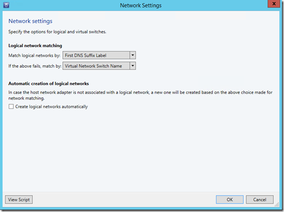
Since we’ll be setting up all our network objects, we’ll want to disable the user-friendly auto-creation of logical networks. In the VMM UI, do this from the General section of the Settings pane by right-clicking on the Network Settings and selecting Properties :

Then, deselect Create logical networks automatically and click OK :
From PowerShell, this is done with:
|
001
|
Set-SCVMMServer -AutomaticLogicalNetworkCreationEnabled $false;
|
Host Groups
Host Groups provide a way to group together hosts in a logical manner for easier management. When we create Network Sites, we’ll need to provide the Host Groups that belong to the site. To create a host group, on the Fabric pane in the VMM UI, expand Servers , right-click All Hosts and select Create Host Group :

A new object will be created that you can name:

Create groups named Management and Tenant:
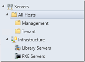
The Management group will contain the Hyper-V hosts that house our management components (VMM, SQL, Domain Controllers, DNS, and such) and the Tenant group will contain Hyper-V hosts that will run tenant VMs.
To create these groups in PowerShell:
|
001
002 003 |
$allHostsGroup = Get-SCVMHostGroup -Name "All Hosts";
$mgmtGroup = New-SCVMHostGroup -Name "Management" -ParentHostGroup $allHostsGroup; $tenantGroup = New-SCVMHostGroup -Name "Tenant" -ParentHostGroup $allHostsGroup; |
Hosts
Now that we have our host groups, we need to add hosts. In the VMM UI, right-click the desired host group and select Add Hyper-V Hosts and Clusters :

Follow the dialog to select the Run As Account and provide the cluster name (in my case HOSTCLUSTER ):

After completing the dialog for each cluster, the host clusters should appear under the desired host groups:

The equivalent PowerShell is:
|
001
002 |
$mgmtCluster = Add-SCVMHostCluster -Name "MGMTCLUSTER.contoso.com" -VMHostGroup $mgmtGroup -Credential $domainAdminRAA -RemoteConnectEnabled $true;
$tenantCluster = Add-SCVMHostCluster -Name "HOSTCLUSTER.contoso.com" -VMHostGroup $tenantGroup -Credential $domainAdminRAA -RemoteConnectEnabled $true; |
Now we can begin creating network objects.
Logical Networks and Network Sites
The first network components to create are our Logical Networks. Logical Networks bind VM Networks to a group of Network Sites to dictate the connectivity of the VM Networks. Additionally, IP subnets under a Logical Network will bind to particular Network Sites. Another name for a Network Site is a Logical Network Definition.
We’ll be creating two logical networks and their settings will differ slightly. Recall that, in my environment, my management network is the native VLAN and each tenant network will be its own VLAN. So, the Hyper-V hosts will need to tag the VLAN ID on outgoing traffic for tenant VMs and we must supply this information. First, we’ll create the Management network.
To create a Logical Network, in the Fabric pane, expand Networking , right-click Logical Networks , and select Create Logical Network :

Name the network Management , and click Next :

On the next page, we define our network site. Click Add to create a new site. Since this is the management network, it should be present on all hosts, so select the All Hosts host group.

In my topology, the management network is the untagged VLAN on all my Hyper-V hosts. To indicate this, I’ll enter a 0 for the VLAN ID. My IP subnet is 10.80.0.0/24 , so this is what I enter. Click Next and then Finish .
In PowerShell, the steps are:
|
001
002 003 |
$mgmtLogicalNetwork = New-SCLogicalNetwork -Name "Management" -LogicalNetworkDefinitionIsolation $false -EnableNetworkVirtualization $false -UseGRE $false -IsPVLAN $false;
$mgmtSubnetVlan = New-SCSubnetVLan -Subnet "10.80.0.0/24" -VLanID 0; $mgmtLogicalNetworkDefinition = New-SCLogicalNetworkDefinition -Name "Management" -LogicalNetwork $mgmtLogicalNetwork -VMHostGroup $allHostsGroup -SubnetVLan $mgmtSubnetVlan; |
The cmdlet New-SCLogicalNetworkDefinition corresponds to creating a new Network Site under a Logical Network with the associated New-SCSubnetVLan creating the VLAN/IP row.
For the tenant network, we’ll be creating different VLANs for each tenant. To this end, I’ll separate the process into two steps. First, create the Logical Network, choosing VLAN-based independent networks :

Do not create a Network Site and complete the wizard.
In PowerShell, this is:
|
001
|
$tenantLogicalNetwork = New-SCLogicalNetwork -Name "Tenant" -LogicalNetworkDefinitionIsolation $true -EnableNetworkVirtualization $false -UseGRE $false -IsPVLAN $false;
|
Once the Logical Network is created, you can add a Network Site for each tenant. To add a network site to an additional Logical Network, simply right-click the Logical Network and select Properties :

In the Properties dialog, click Network Sites and a new site can be added as before:

Click OK when finished.
In PowerShell:
|
001
002 |
$tenantSubnetVlan = New-SCSubnetVLan -Subnet "10.80.2.0/24" -VLanID 802;
$tenantLogicalNetworkDefinition = New-SCLogicalNetworkDefinition -Name "Fabrikam" -LogicalNetwork $tenantLogicalNetwork -VMHostGroup @($tenantGroup) -SubnetVLan $tenantSubnetVlan; |
Subsequent networks for additional tenants can be created in the same way.
The next component to configure will be the Uplink Port Profiles.
Uplink Port Profiles
An Uplink Port Profile defines host NIC settings. When you consider the clusters in my environment, Logical Network connectivity looks like this:

In the diagram above, I’ll need to define a different Uplink Port Profile for each behavior of a host NIC. The Uplink Port Profile serves as a template for host NIC settings, so it can be reused. In my environment, I’ll define one Uplink Port Profile for my Management hosts and one for my Tenant hosts.
To create an Uplink Port Profile, in the Fabric pane, expand Networking , right-click Port Profiles , and select Create Hyper-V Port Profile :

In the dialog, enter Management for the name and select Uplink port profile :

If the switch that connects to my hosts were configured for NIC teaming, I could choose the teaming mode here. In my environment, my switch is unaware of any teaming settings, I’ll go with Switch Independent . On the next page, you can select the appropriate Network Site for the Management hosts:

Finish the wizard.
In PowerShell:
|
001
|
$mgmtUplinkPortProfile = New-SCNativeUplinkPortProfile -Name "Management" -LogicalNetworkDefinition $mgmtLogicalNetworkDefinition -EnableNetworkVirtualization $false -LBFOLoadBalancingAlgorithm "HostDefault" -LBFOTeamMode "SwitchIndependent";
|
I’ll do this again for my Tenant Uplink Port Profile, but this time I’ll enable both sites:

In PowerShell:
|
001
|
$tenantUplinkPortProfile = New-SCNativeUplinkPortProfile -Name "Tenant" -LogicalNetworkDefinition @($mgmtLogicalNetworkDefinition, $tenantLogicalNetworkDefinition) -EnableNetworkVirtualization $false -LBFOLoadBalancingAlgorithm "HostDefault" -LBFOTeamMode "SwitchIndependent";
|
Next, I'll want to create the Logical Switches so I can assign them to my hosts.
Logical Switches
If I were using any switch extensions for Hyper-V, I’d want to install those before proceeding. I’ll be creating two Logical Switches, one for Management hosts and one for Tenant hosts. To create a Logical Switch, in the Fabric pane, expand Networking , right-click Logical Switches , and select Create Logical Switch :

On the General page, enter Management for the name and click Next :

You can leave the Extensions at their defaults and move on to the Uplink page. On this page, we’ll add the previously created Uplink Port Profile:

Complete the wizard.
The steps in PowerShell can be confusing. The creation of a Logical Switch is a simple task:
|
001
|
$mgmtLogicalSwitch = New-SCLogicalSwitch -Name "Management" -EnableSriov $false -SwitchUplinkMode "Team";
|
However, applying the Uplink Port Profile requires creating a construct that isn’t exposed to the UI. On the Uplink page, what is created under the covers is called an Uplink Port Profile Set and it binds the Logical Switch to a set of Uplink Port Profiles. In PowerShell, this corresponds to:
|
001
|
$mgmtUplinkPortProfileSet = New-SCUplinkPortProfileSet -Name "Management" -LogicalSwitch $mgmtLogicalSwitch -NativeUplinkPortProfile $mgmtUplinkPortProfile;
|
One caveat is that the UI also generates a GUID to attach to the Name of the Uplink Port Profile Set. If you wanted to also do things this way, you could:
|
001
002 |
$mgmtUplinkPortProfileSetGUID = [System.Guid]::NewGuid().toString();
$mgmtUplinkPortProfileSet = New-SCUplinkPortProfileSet -Name "Management_$mgmtUplinkPortProfileSetGUID" -LogicalSwitch $mgmtLogicalSwitch -NativeUplinkPortProfile $mgmtUplinkPortProfile; |
The process is the same for creating the Tenant Logical Switch.
Before adding the Logical Switches to the hosts, we’ll want to create some VM Networks.
VM Networks
When creating VM Networks that do not use network virtualization, there aren’t many options. We’ll create two VM Networks, one for Management and one for the Fabrikam Tenant. If we had additional tenants, we could create additional VM Networks for each Network Site in the Tenant Logical Network.
First we’ll create the Management VM Network. To create a VM Network, in the VMs and Services pane, right-click VM Networks and select Create VM Network :

Name the VM Network Management and finish the wizard. In PowerShell:
|
001
|
$mgmtVMNetwork = New-SCVMNetwork -Name "Management" -LogicalNetwork $mgmtLogicalNetwork -IsolationType "NoIsolation";
|
Now create another VM Network, this time naming it Fabrikam and proceed to the Isolation Options page. Select Specify a VLAN to choose the appropriate site that corresponds to this tenant:

Finish the wizard. The PowerShell for this is:
|
001
002 |
$tenantVMNetwork = New-SCVMNetwork -Name "Fabrikam" -LogicalNetwork $tenantLogicalNetwork -IsolationType "VLANNetwork";
$vmSubnet = New-SCVMSubnet -Name "Fabrikam" -LogicalNetworkDefinition $tenantLogicalNetworkDefinition -SubnetVLan $tenantSubnetVlan -VMNetwork $tenantVMNetwork; |
Now we can configure our hosts.
Applying Network Settings to Hosts
To make my hosts ready for VM deployment, I’ll need to add a Logical Switch to each host. This can be a headache for some because of connectivity, so I’ll try to be clear about the process. In my environment, my hosts have two network adapters. Both are VLAN trunks and connectivity to the hosts goes on the native VLAN for the trunk. However, since there are two NICs in the host, both NICs have registered their IP addresses with DNS. As such, the ordering of the NICs matters. When we add a Logical Switch using teaming, the process VMM follows is:
- Create a new LBFO team adapter.
- Create a virtual network adapter on the host and bind it to the LBFO adapter.
- Install any necessary switch extensions.
- Add a Hyper-V vSwitch and bind it to the LBFO adapter.
- Apply any necessary properties to the vSwitch.
The Hyper-V vSwitch is then associated with the Logical Switch in VMM and configuration is complete. Now, VMM queues up this set of actions all at once, as connectivity to the host will be lost during the process. The complication is step #2 above. When the virtual network adapter (also called a tNIC) is created on the host, the tNIC spoofs the MAC address of the first NIC in the team, thereby retaining it’s IP address. This is why ordering of the NICs matters: if VMM is communication with the other NIC when this process starts, it will lose connectivity to the host and the job will fail half-completed.
To avoid connectivity issues, I will first check which IP VMM uses to communicate with the host before creating the Logical Switch on the host. To do this, I can simply ping the host and check its IP:

Next, in the Fabric pane, expand Servers , expand the Management host group, and select the management cluster. Right-click the host and select Properties :

In the properties dialog, under Hardware , locate the network adapter with that IP address and take note (Ethernet 4):

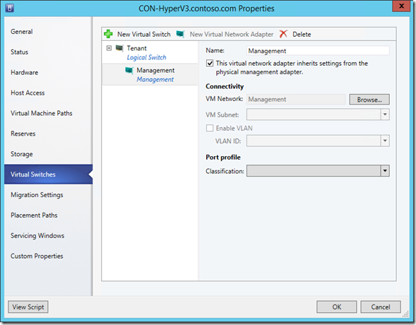
Under Virtual Switches , click New Virtual Switch and select New Logical Switch :

Select Management as the Logical Switch and add the two adapters, listing the adapter with the appropriate IP (Ethernet 4) first:

In order to maintain connectivity to the host, we’ll add a management NIC. To do this, click New Virtual Network Adapter , name it Management , and ensure it has connectivity to the Management VM Network (which is bound to the Management Logical Network):

Click OK to add the Logical Switch and follow the same process for each host in the cluster. This required a number of clicks, so the PowerShell is accordingly more complicated, though we follow the same process. We’ll need to:
- Get the IP address of the host.
- Find the NIC with that IP.
- Assign that NIC to the Uplink Port Profile set.
- Get all the other NICs on the host.
- Assign each of those NICs to the Uplink Port Profile set.
- Create the Logical Switch on the host, assigning the ordered list of NICs, the Logical Switch, and creating the Management adapter with the appropriate VM Network (switch extensions will be installed by VMM as necessary).
Also, since we’ll lose connectivity to the host during the process, we’ll want to queue this up as a single job group so all actions are done at once. Lastly, since we’ll perform this action on all hosts in the Management cluster, I’ll adjust the PowerShell as such, giving us:
|
001
002 003 004 005 006 007 008 009 010 011 012 013 014 015 016 017 018 019 020 021 022 023 024 |
# Get the names of all hosts in cluster
$nodeNames = $mgmtCluster.Nodes.Name; # Build a hash table mapping hostname to IP $nodeIPs = @{}; foreach($name in $nodeNames) { # Get the main IP of host $nodeIPs[$name] = @([System.Net.Dns]::GetHostAddresses($name).IPAddressToString)[0]; } # Run on each host in cluster foreach($node in $mgmtCluster.Nodes) { # Create Job Group GUID $jobgroupGUID = [System.Guid]::NewGuid().ToString(); # Assign settings to NIC with main IP $firstNetworkAdapter = Get-SCVMHostNetworkAdapter -VMHost $node | ?{$_.IPAddresses -contains $nodeIPs[$node.Name]}; Set-SCVMHostNetworkAdapter -VMHostNetworkAdapter $firstNetworkAdapter -UplinkPortProfileSet $mgmtUplinkPortProfileSet -JobGroup $jobgroupGUID; # Assign settings to other NICs $otherNetworkAdapters = Get-SCVMHostNetworkAdapter -VMHost $node | ?{$_.IPAddresses -notcontains $nodeIPs[$node.Name]}; $otherNetworkAdapters | %{Set-SCVMHostNetworkAdapter -VMHostNetworkAdapter $_ -UplinkPortProfileSet $mgmtUplinkPortProfileSet -JobGroup $jobgroupGUID}; $networkAdapters = @($firstNetworkAdapter, $otherNetworkAdapters); # Create Logical Switch configuration New-SCVirtualNetwork -VMHost $node -VMHostNetworkAdapters $networkAdapters -LogicalSwitch $mgmtLogicalSwitch -JobGroup $jobgroupGUID -CreateManagementAdapter -ManagementAdapterName "Management" -ManagementAdapterVMNetwork $mgmtVMNetwork; # Run the job on the host Set-SCVMHost -VMHost $node -JobGroup $jobgroupGUID; } |
Next, I’ll need to do this for my tenant cluster. The steps are mostly similar but I’ll be adding the other Logical Switch. When assigning the Management NIC connectivity, I’ll need to choose the Management VM Network. To do this, click the Browse… button:

In the pop-up, select the Management VM Network and click OK :

Now, click OK to add the Logical Switch:
Do this for each host in the tenant cluster. The PowerShell is very similar to before:
|
001
002 003 004 005 006 007 008 009 010 011 012 013 014 015 016 |
$nodeNames = $tenantCluster.Nodes.Name;
$nodeIPs = @{}; foreach($name in $nodeNames) { $nodeIPs[$name] = @([System.Net.Dns]::GetHostAddresses($name).IPAddressToString)[0]; } foreach($node in $tenantCluster.Nodes) { $jobgroupGUID = [System.Guid]::NewGuid().ToString(); $firstNetworkAdapter = Get-SCVMHostNetworkAdapter -VMHost $node | ?{$_.IPAddresses -contains $nodeIPs[$node.Name]}; Set-SCVMHostNetworkAdapter -VMHostNetworkAdapter $firstNetworkAdapter -UplinkPortProfileSet $tenantUplinkPortProfileSet -JobGroup $jobgroupGUID; $otherNetworkAdapters = Get-SCVMHostNetworkAdapter -VMHost $node | ?{$_.IPAddresses -notcontains $nodeIPs[$node.Name]}; $otherNetworkAdapters | %{Set-SCVMHostNetworkAdapter -VMHostNetworkAdapter $_ -UplinkPortProfileSet $tenantUplinkPortProfileSet -JobGroup $jobgroupGUID}; $networkAdapters = @($firstNetworkAdapter, $otherNetworkAdapters); # Notice: We use $mgmtVMNetwork here New-SCVirtualNetwork -VMHost $node -VMHostNetworkAdapters $networkAdapters -LogicalSwitch $tenantLogicalSwitch -JobGroup $jobgroupGUID -CreateManagementAdapter -ManagementAdapterName "Management" -ManagementAdapterVMNetwork $mgmtVMNetwork; Set-SCVMHost -VMHost $node -JobGroup $jobgroupGUID | Out-Null; } |
As this task is a bit longer than others, you could write a more elegant script to handle all the host configurations with fewer lines of code and run it in parallel using the – RunAsynchronously flag, but this series isn’t intended to be a PowerShell optimization lesson.
Usage
At this point, my environment is ready for tenant VM deployment. When I deploy a VM to the Fabrikam VM Network, it will exist in complete isolation. Any other VMs that I need on my management network can be deployed to my management cluster.
It’s important to note that VMs deployed to my tenant network rely on the ability of my network to route its VLAN. Additionally, if I need access from the management network into a tenant network, I’ll need to either configure a Layer-3 device to provide inter-VLAN routing or create a VM with two NICs: one on the tenant network and one on the management.
Next Time
I hope you could follow these steps and gained a little understanding of VMM networking. The way things are currently configured, any time a new tenant is brought into my network, I’ll have to create a new VLAN for it, and that will require configuration of my network devices. Moving forward, we’ll be setting up virtual networking to alleviate the pain of onboarding new tenants.